Table of Contents
Advertisement
Installation, Operation, and Maintenance
Upflow/Horizontal Left/Right
Gas-Fired, Single Stage Induced Draft Furnace with Variable
Speed Blower Motor
U U p p f f l l o o w w , , H H o o r r i i z z o o n n t t a a l l R R i i g g h h t t / / L L e e f f t t
(For use with Natural Gas only.)
Single Stage
L8V1A040U3VSBA
L8V1A060U3VSBA
L8V1B080U4VSBA
L8V1C100U5VSBA
N N o o t t e e : : This product complies with SJVUAPCD 4905 and SCAQMD 1111 with
NOx levels below 14 ng/J.
WARNING
FIRE HAZARD!
Failure to follow this Warning could result in property damage, severe personal
injury, or death.
This Warning applies to installations with a ammable refrigeration system.
The furnace must be powered except for service. The furnace shall be installed
and connected according to installation instructions and wiring diagrams that
are provided with the evaporator coil.
Only qualified personnel should install and service the equipment. The installation, starting up, and servicing of heating, ventilating, and air-conditioning
equipment can be hazardous and requires specific knowledge and training. Improperly installed, adjusted or altered equipment by an unqualified person
could result in death or serious injury. When working on the equipment, observe all precautions in the literature and on the tags, stickers, and labels that
are attached to the equipment.
May 2023
S S A A F F E E T T Y Y W W A A R R N N I I N N G G
L L 8 8 V V 1 1 - - S S V V X X 0 0 0 0 1 1 - - 1 1 A A - - E E N N
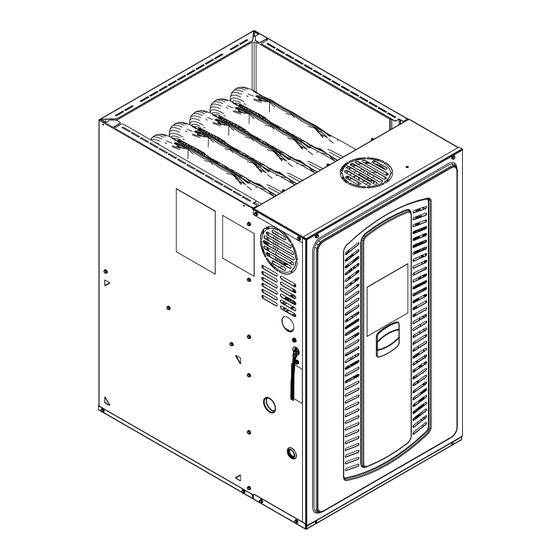
N N o o t t e e : : Graphics in this document are for
representation only. Actual model may
differ in appearance.
L8V1-SVX001-1A-EN
Advertisement
Table of Contents

Subscribe to Our Youtube Channel
Related Manuals for Trane L8V1A040U3VSBA


Summary of Contents for Trane L8V1A040U3VSBA
- Page 1 U U p p f f l l o o w w , , H H o o r r i i z z o o n n t t a a l l R R i i g g h h t t / / L L e e f f t t (For use with Natural Gas only.) Single Stage L8V1A040U3VSBA L8V1A060U3VSBA L8V1B080U4VSBA...
- Page 2 SAFETY SECTION NON-CONDENSING FURNACES I I m m p p o o r r t t a a n n t t : : — This document pack contains a wiring W W A A R R N N I I N N G G diagram and service information.
- Page 3 S S A A F F E E T T Y Y S S E E C C T T I I O O N N N N O O N N - - C C O O N N D D E E N N S S I I N N G G F F U U R R N N A A C C E E S S W W A A R R N N I I N N G G W W A A R R N N I I N N G G W W A A R R N N I I N N G G ! !
- Page 4 S S A A F F E E T T Y Y S S E E C C T T I I O O N N N N O O N N - - C C O O N N D D E E N N S S I I N N G G F F U U R R N N A A C C E E S S W W A A R R N N I I N N G G W W A A R R N N I I N N G G I I N N S S T T A A L L L L A A T T I I O O N N W W A A R R N N I I N N G G –...
- Page 5 . . C C A A U U T T I I O O N N For more information, visit www.trane.com and www. americanstandardair.com or contact your installing dealer. W W A A T T E E R R D D A A M M A A G G E E ! !
- Page 6 S S A A F F E E T T Y Y S S E E C C T T I I O O N N N N O O N N - - C C O O N N D D E E N N S S I I N N G G F F U U R R N N A A C C E E S S W W A A R R N N I I N N G G C C A A R R B B O O N N M M O O N N O O X X I I D D E E P P O O I I S S O O N N I I N N G G H H A A Z Z A A R R D D ! !
-
Page 7: Table Of Contents
Table of Contents Accessories....... . . 8 Return Air Filters ......34 Document Pack Contents . -
Page 8: Accessories
U U p p f f l l o o w w , , H H o o r r i i z z o o n n t t a a l l R R i i g g h h t t / / L L e e f f t t (For use with Natural Gas only.) Maintenance Single Stage L8V1A040U3VSBA L8V1A060U3VSBA L8V1B080U4VSBA Owner Guide... -
Page 9: Parts List
Parts List Figure 1. L8V1 Parts Exploded View Burner assembly Furnace cabinet assembly Ignitor Blower deck Flame sensor Panel loop interlock (door switch) Burner box limit Blower assembly Orifice Variable speed motor J-tube Vortica blower housing Control assembly RAF – Reverse airflow limit switches IFC - Integrated Furnace Control Heat exchanger assembly Transformer... -
Page 10: Product Specifications
Product Specifications L8V1A040U3VSBA L8V1A060U3VSBA L8V1B080U4VSBA L8V1C100U5VSBA MODEL Upflow / Horizontal Upflow / Horizontal Upflow / Horizontal Upflow / Horizontal TYPE RATINGS Input BTUH 40,000 60,000 80,000 100,000 Capacity BTUH (ICS) 31,700 48,100 63,000 80,200 Temp. Rise (Min. - Max.) °F... -
Page 11: Furnace Installation Guidelines
Furnace Installation Guidelines The following sections give general guidelines for the 11. I I n n t t h h e e C C o o m m m m o o n n w w e e a a l l t t h h o o f f M M a a s s s s a a c c h h u u s s e e t t t t s s , , t t h h i i s s installation of the gas furnaces. -
Page 12: Locations And Clearances
F F u u r r n n a a c c e e I I n n s s t t a a l l l l a a t t i i o o n n G G u u i i d d e e l l i i n n e e s s Locations and Clearances 1. -
Page 13: Outline Drawing
Outline Drawing Table 2. 14.5”, 17.5”, 21” and 24.5” Width Cabinets L8V1-SVX001-1A-EN... -
Page 14: Wiring Diagrams
Wiring Diagrams NOTES: 1. IF ANY OF THE ORIGINAL WIRING AS SUPPLIED WITH THIS FURNACE MUST BE REPLACED, IT MUST BE WITH WIRE HAVING A TEMPERATURE RATING OF AT LEAST 105ºC. 2. FOR PROPER AIRFLOW IN COOLING/HEAT PUMP MODES, Y1 AND/OR Y2 MUST CONNECT FROM THE THERMOSTAT TO THE IFC LOW VOLTAGE TERMINAL STRIP. 3. -
Page 15: Airflow Tables
Airflow Tables Table 3. L8V1A040U3VS Heating Airflow L8V1A040U3VS Furnace Heating Airflow (CFM), Temp. Rise (°F), and Power (Watts) vs. External Static Pressure (iwc) with Filter Heating Capacity = 31,700 Airflow External Static Pressure Target Heating Setting Airflow Temp. Rise Watts Temp. - Page 16 A A i i r r f f l l o o w w T T a a b b l l e e s s Table 5. L8V1A060U3VS Heating Airflow L8V1A060U3VS Furnace Heating Airflow (CFM), Temp. Rise (°F), and Power (Watts) vs. External Static Pressure (iwc) with Filter Heating Capacity = 48,100 Airflow...
- Page 17 A A i i r r f f l l o o w w T T a a b b l l e e s s Table 7. L8V1B080U4VS Heating Airflow L8V1B080U4VS Furnace Heating Airflow (CFM), Temp. Rise (°F), and Power (Watts) vs. External Static Pressure (iwc) with Filter Heating Capacity = 63,000 Airflow...
- Page 18 A A i i r r f f l l o o w w T T a a b b l l e e s s Table 8. L8V1B080U4VS Cooling Airflow (continued) L8V1B080U4VS Furnace Cooling Airflow (CFM) and Power (Watts) vs. External Static Pressure with Filter CFM / WATTS 1779 / 513 1779 / 607...
- Page 19 A A i i r r f f l l o o w w T T a a b b l l e e s s Table 10. L8V1C100U5VS Cooling Airflow (continued) L8V1C100U5VS Furnace Cooling Airflow (CFM) and Power (Watts) vs. External Static Pressure with Filter CFM / WATTS 1773 / 364 1769 / 430...
-
Page 20: Furnace General Installation
Furnace General Installation The following sections give general instructions for the installation of the gas furnaces. Furnace Panel Removal Note: For the L8V1 furnace, a 1/4" nut driver is required to remove the two screws at the top of the front panel. The front panel can then be removed by lifting upwards. -
Page 21: Gas Piping
F F u u r r n n a a c c e e G G e e n n e e r r a a l l I I n n s s t t a a l l l l a a t t i i o o n n Gas Piping Important: The furnace default is left side gas piping. - Page 22 F F u u r r n n a a c c e e G G e e n n e e r r a a l l I I n n s s t t a a l l l l a a t t i i o o n n Furnace in horizontal right orientation with gas piping out top Furnace in horizontal right orientation with gas piping out bottom Note: For ease of installation, optional accessory part PIP02095 is...
-
Page 23: Combustion And Input Check
F F u u r r n n a a c c e e G G e e n n e e r r a a l l I I n n s s t t a a l l l l a a t t i i o o n n Combustion and Input Check Gas Valve Adjustment 1. -
Page 24: High Altitude Derate
F F u u r r n n a a c c e e G G e e n n e e r r a a l l I I n n s s t t a a l l l l a a t t i i o o n n High Altitude Derate 9. -
Page 25: General Venting
F F u u r r n n a a c c e e G G e e n n e e r r a a l l I I n n s s t t a a l l l l a a t t i i o o n n General Venting Multistory and common venting are permitted for these furnaces. - Page 26 F F u u r r n n a a c c e e G G e e n n e e r r a a l l I I n n s s t t a a l l l l a a t t i i o o n n EXTERNAL MASONRY CHIMNEY Venting of fan assisted appliances into external chimneys (one or more walls Gas Vent Termination...
-
Page 27: Air For Combustion And Ventilation
F F u u r r n n a a c c e e G G e e n n e e r r a a l l I I n n s s t t a a l l l l a a t t i i o o n n Air for Combustion and C C o o n n f f i i n n e e d d spaces are installations with less than 50 cu. - Page 28 F F u u r r n n a a c c e e G G e e n n e e r r a a l l I I n n s s t t a a l l l l a a t t i i o o n n CONFINED CONFINED SPACE FURNACE...
-
Page 29: Duct Connections
F F u u r r n n a a c c e e G G e e n n e e r r a a l l I I n n s s t t a a l l l l a a t t i i o o n n Duct Connections Air duct systems should be installed in accordance with standards for When the furnace is located in a utility room adjacent to the living... - Page 30 F F u u r r n n a a c c e e G G e e n n e e r r a a l l I I n n s s t t a a l l l l a a t t i i o o n n Table 11.
- Page 31 F F u u r r n n a a c c e e G G e e n n e e r r a a l l I I n n s s t t a a l l l l a a t t i i o o n n Table 12.
- Page 32 F F u u r r n n a a c c e e G G e e n n e e r r a a l l I I n n s s t t a a l l l l a a t t i i o o n n Table 12.
- Page 33 F F u u r r n n a a c c e e G G e e n n e e r r a a l l I I n n s s t t a a l l l l a a t t i i o o n n I I n n s s t t a a l l l l a a t t i i o o n n I I n n s s t t r r u u c c t t i i o o n n s s 12.
-
Page 34: Return Air Filters
F F u u r r n n a a c c e e G G e e n n e e r r a a l l I I n n s s t t a a l l l l a a t t i i o o n n Return Air Filters TYPICAL AIR FILTER INSTALLATIONS RETURN AIR FILTERS FOR MODULAR BLOWER IN... -
Page 35: Electrical Connections
F F u u r r n n a a c c e e G G e e n n e e r r a a l l I I n n s s t t a a l l l l a a t t i i o o n n Electrical Connections Make wiring connections to the unit as indicated on enclosed wiring diagram. - Page 36 F F u u r r n n a a c c e e G G e e n n e e r r a a l l I I n n s s t t a a l l l l a a t t i i o o n n COMMUNICATING CONTROLS WITH NON-COMMUNICATING L8V1 FURNACE AND COMMUNICATING VS COOLING/HP Communicating...
-
Page 37: General Start-Up And Adjustment
General Start-up and Adjustment The following sections give instructions for the general start-up and adjustment of the gas furnaces. Preliminary Inspections With gas and electrical power "OFF", ensure: Turn knob on main gas valve within the unit to the "OFF" position. Turn the external gas valve to "ON". -
Page 38: Options
Furnace Combustion Air Exhaust Options Note: Default is left side for electric and gas connections. The following sections give instructions for the I I m m p p o o r r t t a a n n t t : : When looking at the different orientations, different furnace orientations and the options for the direction of the combustion air exhaust venting the exhaust combustion air. -
Page 39: Instructions
F F u u r r n n a a c c e e C C o o m m b b u u s s t t i i o o n n A A i i r r E E x x h h a a u u s s t t O O p p t t i i o o n n s s Inducer Venting Conversion Instructions Pressure Switch locations Important: After deciding the orientation of the flue outlet, cut the... - Page 40 F F u u r r n n a a c c e e C C o o m m b b u u s s t t i i o o n n A A i i r r E E x x h h a a u u s s t t O O p p t t i i o o n n s s Upflow orientation with right side venting Important: The combustion air duct MUST be installed on C100 upflow applications.
- Page 41 F F u u r r n n a a c c e e C C o o m m b b u u s s t t i i o o n n A A i i r r E E x x h h a a u u s s t t O O p p t t i i o o n n s s Horizontal right orientation with right side venting No changes need to be made to the inducer when installing the furnace in upflow position with the combustion air vented through the...
-
Page 42: Integrated Furnace Control Menu
Integrated Furnace Control Menu L8V1-SVX001-1A-EN... - Page 43 I I n n t t e e g g r r a a t t e e d d F F u u r r n n a a c c e e C C o o n n t t r r o o l l M M e e n n u u L8V1-SVX001-1A-EN...
-
Page 44: Belly Band Location
I I n n t t e e g g r r a a t t e e d d F F u u r r n n a a c c e e C C o o n n t t r r o o l l M M e e n n u u Note: During run test mode, depressing the option key will allow the user to hold (HLD) that test sequence if measurements want to be taken. -
Page 45: Codes
Integrated Furnace Control Display Codes Inducer with ECM Blower Motor Idle Gas Heating Calculated Airflow (Followed by Airflow times 10) Continuous Fan First Stage Cooling Second Stage Cooling First Stage Heat Pump Second Stage Heat Pump Defrost Mode Menu Options Active Alarm Menu Last 6 Faults (To clear —... -
Page 46: Setting Airflow
Setting Airflow With all ductwork connected and a clean filter in place, measure the External Static Pressure (ESP) of the unit in locations below. Use the appropriate airflow table for the furnace and outdoor unit installed. Measurements must be made prior to the evaporator coil, if equipped, Evaporator and after the filter. -
Page 47: Led Fault Codes
LED Fault Codes POSSIBLE CAUSE/ACTION ERROR ERROR EXPLANATION Loss of IRQ Replace IFC Internal IFC failure Retries Exceeded (5 Flame never sensed (5 retries, 6 total results Gas valve not energized, flame sensor faulty, low E2.1 retries, 6 total) in one hour lockout) manifold pressure Recycles Exceeded (9 Flame sensed and lost (9 recycles, 10 total... - Page 48 L L E E D D F F a a u u l l t t C C o o d d e e s s POSSIBLE CAUSE/ACTION ERROR ERROR EXPLANATION Verify correct motor HP in this document. PM motor information does not match the PM Motor ID Error Replacement motor is not approved motor installed...
- Page 49 L L E E D D F F a a u u l l t t C C o o d d e e s s Table 17. Inducer Pressure Transducer L8V1A040U3VS* Inducer Mode Pressure (in/H20) VDC Pins 2 & 3 Pre-Purge –...
- Page 50 L L E E D D F F a a u u l l t t C C o o d d e e s s Table 18. Pressure Transducer E18 Source Voltage 5Vdc Pins 1-2 (GR-RD) Transducer Signal Vdc Pins 1-3 (GR-BK @ E18) Hot Header Pressure Inches W.C.
-
Page 51: Sequence Of Operation
Sequence of Operation E E A A C C a a n n d d H H U U M M T T i i m m i i n n g g 6. Once flame sense has been established, the igniter is de-energized, the blower on timer begins and the •... - Page 52 S S e e q q u u e e n n c c e e o o f f O O p p e e r r a a t t i i o o n n T T w w o o S S t t a a g g e e C C o o o o l l i i n n g g •...
-
Page 53: Periodic Servicing Requirements
Periodic Servicing Requirements 1. GENERAL INSPECTION – E E x x a a m m i i n n e e t t h h e e f f u u r r n n a a c c e e h. - Page 54 P P e e r r i i o o d d i i c c S S e e r r v v i i c c i i n n g g R R e e q q u u i i r r e e m m e e n n t t s s M M a a i i n n t t e e n n a a n n c c e e I I n n s s t t r r u u c c t t i i o o n n s s e.
- Page 55 N N o o t t e e s s L8V1-SVX001-1A-EN...
- Page 56 About Trane and American Standard Heating and Air Conditioning Trane and American Standard create comfortable, energy efficient indoor environments for residential applications. For more information, please visit www.trane.com or www.americanstandardair.com. The manufacturer has a policy of continuous data improvement and it reserves the right to change design and specifications without notice. We are committed to using environmentally conscious print practices.
Need help?
Do you have a question about the L8V1A040U3VSBA and is the answer not in the manual?
Questions and answers