Avid Technology NEXIS Setup And Maintenance Manual
Hide thumbs
Also See for NEXIS:
- Setup and maintenance manual (85 pages) ,
- Setup and maintenance manual (57 pages)
Table of Contents
Advertisement
Advertisement
Table of Contents

Related Manuals for Avid Technology NEXIS


Summary of Contents for Avid Technology NEXIS
- Page 1 Avid NEXIS® Setup and Maintenance Guide Version 2023.7.0...
- Page 2 This guide is protected by copyright. This guide is for your personal use and may not be reproduced or distributed, in whole or in part, without permission of Avid. Reasonable care has been taken in preparing this guide; however, it may contain omissions, technical inaccuracies, or typographical errors. Avid Technology, Inc.
- Page 3 YOU MAY HAVE WHICH VARY FROM STATE TO STATE. Avid NEXIS Setup and Maintenance Guide • Revised July 2023 • This document is distributed by Avid in online (electronic) form only, and is not available for purchase in printed form.
- Page 4 Corrected Media Pack drive sizes March 2021 2021.3.0 Updated system drive capacities July 2020 2020.5.0 Added Avid NEXIS | FS description, cautions when adding Engines to an existing system . Some document restructuring. May 2020 2020.5.0 Avid NEXIS | All-Mirror support April 2020 2020.3.0...
-
Page 5: Table Of Contents
Installing Media Packs in 2U and 4U Engines Installing Media Packs in 5U Chassis Connecting the Equipment to Power 3 Installing the Software and Setting up the Avid NEXIS System System Setup Information Understanding the Shared Name Space Understanding System Licenses Registering the System and Downloading the Avid NEXIS Software Configuring the Computer’s IP Address... - Page 6 Collecting Logs for Customer Care Understanding Hardware Faults Adding an Engine to a System Adding an Avid NEXIS | F2X (Expansion Chassis) to a System Adding Media Packs to an Engine About Drive Failures Identifying the Slot Number for a Failing or Failed Drive...
- Page 7 Symbols Product Safety Warning Important Safety Instructions Rack-Mount Safety Instructions LED Safety Notices Environmental Compliance...
-
Page 8: Using This Guide
Using This Guide ® The Avid NEXIS software-defined storage system provides a high-performance distributed file system that contains high-capacity shared media storage for workgroups of connected devices. This user’s guide describes how to connect your client system to the storage system, mount Workspaces, and configure your system for best performance. -
Page 9: If You Need Help
Using This Guide If You Need Help If you are having trouble using your Avid product: 1. Retry the action, carefully following the instructions given for that task in this guide. It is especially important to check each step of your workflow. 2. -
Page 10: Avid Nexis System Overview
The System Director is a process or service that manages and maintains the Avid NEXIS file system. In any Avid NEXIS configuration, there is only one System Director, which runs on one Controller, either in an Engine (and is called an embedded System Director) or in a System Director Appliance (SDA), which is sometimes called an external System Director. -
Page 11: Avid Nexis Models
1 Avid NEXIS System Overview Avid NEXIS All-Mirror Engines The System Director Appliance cannot be used with Avid NEXIS | PRO 40TB or Avid NEXIS | PRO+ systems. In a configuration with no System Director Appliance, the first Engine that you configure runs the System Director for the entire system. - Page 12 Both Controllers in an Engine or a System Director Appliance must be the same type, with the same label. In Avid NEXIS versions prior to v2021.3.0, after the system completes its boot cycle, all LEDs on the back of the Controller remain on. In Avid NEXIS version v2021.3.0 and later, after the boot cycle all LEDs on the back of the Controller turn off.
- Page 13 Controller connectors and ports, and the LED colors and flash patterns are described in the following figures and tables. Features that are not identified in the figures and tables are not used in the Avid NEXIS implementation. Do not connect anything to unidentified ports.
- Page 14 SAS ports Used only in the Avid NEXIS | F2 to connect one or both Controllers to the SAS ports on the I/O Modules in an Avid NEXIS | F2X. See "Rack-Mounting the Equipment" on page 33 for how to connect the cables.
- Page 15 I/O Module Features and Functionality The Avid NEXIS | F2X has two I/O modules that connect to an Avid NEXIS | F2. The I/O modules provide data connection to the Controllers in an Avid NEXIS | F2, which manages both chassis. The I/O modules do not support direct switch connections.
- Page 16 Feature Description If the Avid NEXIS | F2 has redundant Controllers, connect the top Controller to the top I/O module, and connect the bottom Controller to the bottom I/O module. Do not connect one Controller to both I/O modules, and do not cross connect two Controllers to both I/O modules.
- Page 17 USM version 1.37/1.37a factory Avid NEXIS | E5 All-Mirror installed Controller E5 NL 2x10GbE Avid NEXIS | E5 NL Avid NEXIS | E5 NL G2 2x10GbE Avid NEXIS | E5 NL USM version 1.37/1.37a factory installed E-Series Controller Features and LEDs The only visible difference between the Controllers is the identification label text.
- Page 18 "Connecting the Equipment to a Switch" on page 52). The Avid NEXIS | E5 NLcomes with QSFP to SFP+ adapters for these ports and supports connection only to a 10GbE switch. For a single-port connection to a switch, use the left port (gx0). If using link aggregation (NIC teaming), connect both ports (gx0 and gx1) to one or more switches.
-
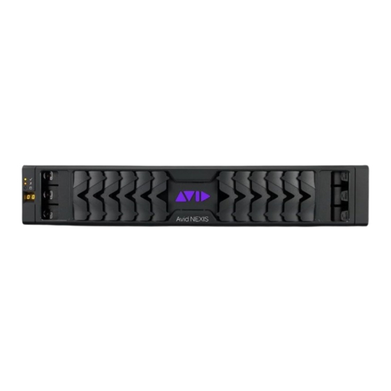
Page 19: Front Views
"Controllers and I/O Modules" on page 12) in Avid NEXIS | E2 or Avid NEXIS | E2 SSD engines no longer support new activations of Avid NEXIS | Cloudspaces if they are also serving as the System Director for a shared-storage system. Avid NEXIS | E2 and Avid NEXIS | E2 SSD Controllers with 16GB of memory can be used in the storage-only Engines in a Cloudspaces configuration. - Page 20 1 Avid NEXIS System Overview 5U Sideplane and Drive Drawer Status Panel (Four Panels) The sideplane and drive drawer status panels indicate the health of the drives, and show drive activity. 5U Engines: Common Sideplane and Drive Status Panels Feature or LED...
-
Page 21: Rear Views
Serial Number Location On all Avid NEXIS models, the chassis serial number is printed on a label attached to the left rear chassis mounting ear. The following figure shows the location of the serial number label on an Avid NEXIS | E4. - Page 22 The rear of the 2U chassis provides access to the Controllers (or I/O modules) and power/cooling modules (PCMs). The following figure shows a typical 2U chassis. The Avid NEXIS | F2X has two I/O modules in place of Controllers. The Controller details, number of Controllers supported, and their orientation depend on your model;...
-
Page 23: Media Pack And System Drives
If only one Controller is present, it is typically in the left slot. Controllers are identified in error and status messages as 1 (left) and 2 (right). Avid NEXIS | E5 NL comes with a QSFP to SFP+ adapter to connect 10GbE SFP+ optics or cables to a switch. -
Page 24: Drive Labels
The system drive capacities listed here are minimums; Avid reserves the right to supply a larger capacity drive as a replacement. Avid NEXIS SSD system drives cannot be removed from one system and used as a replacement in another system. The system drives are initialized as a mirrored pair during the manufacturing process. -
Page 25: Default Location Of System Drives
1 Avid NEXIS System Overview The drives in the 2U and 4U models have a red lock indicator and two LEDs that show the drive status, explained in the following figure and table. 2U and 4U Drive LEDs Feature Status Indicator Power and activity LED Off—No power... -
Page 26: Chassis Drive Numbering
System Drive Numbering for the System Director Appliance Drive Numbering for 2U (12-Drive) Storage Chassis (Except Avid NEXIS | F2X) Drive Numbering for Avid NEXIS | F2X Drive Numbering for Avid NEXIS | F2 SSD... -
Page 27: Power Supplies And Fans
Power Supplies and Fans Depending on your Avid NEXIS model, the Engine or System Director Appliance has the following number and type of power supply/cooling modules (PCMs) or power supply units (PSUs). The PCMs or PSUs are turned on when the power cord is plugged in and the power switch is on. -
Page 28: Eco Power Supply Units
ECO Power Supply Units Avid NEXIS F-Series and Avid NEXIS | PRO+ systems can use a new generation of power supply units that are more energy efficient and conform to the requirements of the 2009/125/EC Ecodesign Directive, established by the European Environmental Agency. - Page 29 The 764W PCMs are used in all 2U Engines, PROs, and System Director Appliances. The two LEDs marked with battery icons, are not used. 580W Power Supply Features The 580W PCMs are used in all 4U Engines and the Avid NEXIS | F2X Expansion Chassis.
- Page 30 1 Avid NEXIS System Overview The LEDs on the 580W PCM work together to indicate overall module status; in the following table, for each row, all the LEDs must be in the listed state for the definition to apply. 580W Power Supply/Cooling Module LEDs...
- Page 31 1 Avid NEXIS System Overview 2200W PSU LEDs PSU Fail AC Fail Power OK Status (Amber) (Amber) (Green) No AC power to either PSU PSU present but not supplying power Mains AC present, switch on. This PSU is providing power...
- Page 32 1 Avid NEXIS System Overview Fan Module LEDs Fan OK Battery fault Fan fault Status (Green) (Amber) (Amber) Fans OK Communication lost with fan module Controller Reported fan speed is out of tolerance Fans and battery OK Flashing Battery charging...
-
Page 33: Connecting The Equipment
For information about power specification and dimensions see "Specifications and Notices" on page 70. Rack-Mounting the Equipment The Avid NEXIS chassis are designed for 19-inch (483-mm) rack configurations and need rack units corresponding to the chassis size. See "Avid NEXIS Models" on page 11. - Page 34 6. If applicable, connect the SAS cables between the Controllers in the Avid NEXIS | F2 and the I/O modules in the Avid NEXIS | F2X. Connect the cables exactly as follows: If the Avid NEXIS | F2 has a single Controller, connect it to the top I/O module in the Avid NEXIS | F2X.
- Page 35 2 Connecting the Equipment 2. Loosen the four slide adjustment screws so to adjust the bracket rail to the depth of your rack. The adjustment screws are highlighted in a colored circle around the screw. 3. Position the bracket rail between your rack mount rails and adjust the length of the bracket so that it meets the inside of both the front and rear rails as shown in the following figure.
-
Page 36: Installing Media Packs In 2U And 4U Engines
2 Connecting the Equipment the following figure. The rack mount kit provides two sets of bracket extenders: a long pair and short pair. Use the pair of bracket extenders that are most appropriate for your rack. For shallower racks use the longer bracket extenders. -
Page 37: Installing Media Packs In 5U Chassis
2 Connecting the Equipment Model Media Packs Spare Drives Avid NEXIS | F2 SSD Avid NEXIS | F2 Avid NEXIS | F2X Avid NEXIS | PRO 40TB Avid NEXIS | PRO+ Avid NEXIS | E4 To install the Media Pack (and optional spare) drives: 1. -
Page 38: Connecting The Equipment To Power
Connecting the Equipment to Power All Avid NEXIS systems ship with the following quantity and type of North American standard power cables. You might need to obtain power cords from your local reseller or support depot suitable for your locale. - Page 39 Power Cable Type Quantity Avid NEXIS | E5 C19 Female to C20 Male (connects to Power Distribution Unit with C19 Avid NEXIS | E5 NL style connectors) Avid NEXIS | E5 All-Mirror Avid NEXIS | F5 Avid NEXIS | F5 NL Avid does not recommend any specific vendor or model of PDU.
-
Page 40: Installing The Software And Setting Up The Avid Nexis System
Installing the Software and Setting up the Avid NEXIS System The process of installing and setting up the Avid NEXIS Engine and System Director Appliance, if applicable, consists of the following overall steps. This overview assumes you are the owner or end user of the equipment. Rental houses do not need to perform all of these steps. -
Page 41: Understanding The Shared Name Space
Storage System name through the Client Manager UI. You enter the Storage System Name in the Remote Host Settings dialog box in the Client Manager if the Avid NEXIS system is not in the same subnet as the client system (use the System Director IP address if your environment does not use a DNS server; see "System Director Name and IP Address"... - Page 42 IP address. Then you can enter the name into a browser to open the Management Console and log in. Using DNS is required to use the online method to activate an Avid NEXIS license (see the Avid NEXIS Administration Guide for more information about licenses).
-
Page 43: Understanding System Licenses
Capacity licenses are required for any configuration containing an F-Series subscription Engine, and were also previously supplied for Perpetual systems. In existing installations of Avid NEXIS using a capacity license, you can add new Engines with Modular licenses if the entire system is running Avid NEXIS | VFS 2023.7.0 or higher. -
Page 44: Configuring The Computer's Ip Address
3 Installing the Software and Setting up the Avid NEXIS System 2. Download the Avid NEXIS software kit (a zip file) to a computer that you can physically connect to the Engine or System Director Appliance. 3. Unzip the software kit. You will see several files and folders. The file you will install on the Engine is named AvidNEXISSetup_<version>.bin. - Page 45 6. Click Use the following IP address: and enter 169.254.10.20, with a subnet mask of 255.255.255.0, then click OK. By default, the Controller IP address on every Avid NEXIS system is set to 169.254.10.10. You must set the IP address of the computer to 169.254.10.xx, where xx can be anything except 10.
- Page 46 3 Installing the Software and Setting up the Avid NEXIS System To restore the computer’s previous IP address: 1. Open the Windows Control Panel Network and Sharing Center. 2. Click Local Area Connection. 3. Click Properties.
-
Page 47: Installing The Software
3 Installing the Software and Setting up the Avid NEXIS System 4. On the Networking tab, select Internet Protocol Version 4 (TCP/IPv4), then click Properties. 5. Enter the previous IP address (if it was specified) or click Obtain an IP address automatically. -
Page 48: Configuring The Engine, Pro+, Or Sda
Type a Storage System Name. This is the name of the shared storage system containing one or more PRO+s, or Avid NEXIS Engines, including the System Director Appliance, if applicable. Make sure all the PRO+s or Engines/SDA+ that will belong to the same shared-storage system system have the same Storage System Name. - Page 49 3 Installing the Software and Setting up the Avid NEXIS System and Right Controllers, as applicable. Each Engine, PRO+, or SDA+ has a unique Engine name. Only the Storage System Name is common to all members in a shared-storage system.
- Page 50 Engine to an existing shared-storage system. For Avid NEXIS | F2, the modular license is activated only on the F2 and applies to an F2X, regardless of when they are paired.
- Page 51 In a separate browser tab, go to the following page: https://avid.com/license b. Type the Activation ID you received from Avid and the Device ID from the Avid NEXIS system. The Activation ID is verified, and the System ID field is displayed.
-
Page 52: Connecting The Equipment To A Switch
The Avid NEXIS implementation follows the Link Aggregation Control Protocol (LACP) standard. Link aggregation is not supported on Avid NEXIS | PRO+ or Avid NEXIS | PRO 40TB. LACP is supported with one or two Controllers, but if two Controllers are present, it must be enabled on both. -
Page 53: Dual Lacp Connections
3 Installing the Software and Setting up the Avid NEXIS System If you plan to bind the Media Packs as High Performance in a paired Avid NEXIS | F2 and Avid NEXIS | F2X, connect them to a suitable switch as follows:... - Page 54 Dual LACP Connections to Avid NEXIS | F5, Avid NEXIS | F5 NL Dual LACP Connections to Avid NEXIS | E2, Avid NEXIS | E2 All-Mirror, Avid NEXIS | SDA, or Avid NEXIS | E2 SSD Avid NEXIS | E2 SSD supports LACP but only one Controller, upside-down in the bottom slot.
- Page 55 Dual LACP Connections to Avid NEXIS | E5, Avid NEXIS | E5 All-Mirror, or Avid NEXIS | E5 NL Use the supplied QSFP to SFP+ adapter (shown in the following figure) to connect an Avid NEXIS | E5 NL to a...
-
Page 56: Adding And Replacing Hardware
Adding and Replacing Hardware The Avid NEXIS shared-storage system is designed to remain operational if a component fails. You can expand your system (add an Engine, add more Media Packs) to the existing file system in real time, as specified by your system configuration (see the Avid NEXIS ReadMe for configuration limits). -
Page 57: Adding An Engine To A System
An Avid NEXIS system can contain a mix of PRO and PRO+, or E-Series and F-Series Engines with either an Avid NEXIS | SDA, an Avid NEXIS | SDA+, or an Engine running the System Director service for the entire configuration. -
Page 58: Adding An Avid Nexis | F2X (Expansion Chassis) To A System
Avid NEXIS | F2X and the Avid NEXIS | F2 it is paired with. 5. Bind the Media Pack in the Avid NEXIS | F2X to the file system and add it to a Storage Group. See the Avid NEXIS Administration Guide for more information. - Page 59 However, if you want to increase the total capacity of a Storage Group, you can add larger Media Packs and remove the smaller Media Packs. After you remove the last smaller-capacity Media Pack, the Storage Group expands to use the extra space. See the Avid NEXIS Administration Guide for more information.
-
Page 60: About Drive Failures
Media Pack drives and system drives have different effects on the system when they fail: If one system drive fails, the Avid NEXIS Engine continues to operate, but you should replace the failed drive as soon as possible. -
Page 61: Replacing A Drive
You can use a drive from another Avid NEXIS Engine, but if it previously belonged to a Media Pack, you must clear its configuration before the new Engine can use it. See the Avid NEXIS Administration Guide for information about clearing a foreign disk error. - Page 62 4 Adding and Replacing Hardware 3. Make sure the anti-tamper locks are not engaged. The red lock symbol is visible if the drive is locked (see "Drive Types and Sizes" on page 24). Unlock them if necessary by rotating them counterclockwise using a screwdriver with a Torx T20 bit. 4.
-
Page 63: Adding A Redundant Controller
4 Adding and Replacing Hardware Inserting a Drive (5U Chassis) To insert a drive: 1. Open the appropriate drawer. 2. Lower the drive into the slot with the drive capacity label facing towards you. 3. Push the drive downwards and hold it down while sliding the drive carrier plate in the direction shown in the following figure. -
Page 64: About Controller Failures
Click the blue Interfaces tab. c. Enter the IP address for the redundant Controller. d. (Optional) If you plan to enable link aggregation (LACP) on the Controller, see the Avid NEXIS Administration Guide before checking the box. e. Click Save. -
Page 65: Replacing A Controller
4 Adding and Replacing Hardware In any Engine or System Director Appliance with a single Controller, insert the replacement Controller in the same slot as the original factory-installed Controller. See "Controllers and I/O Modules" on page 12 for the required location and orientation for a single-Controller system. Both Controllers in an Engine must be the same type, with the same label. -
Page 66: Replacing An I/O Module
8. Connect the cables to the replacement I/O module (see "Rack-Mounting the Equipment" on page 33 for a figure of the SAS cable connections between the Avid NEXIS | F2 and the Avid NEXIS | F2X). Power Supply Failures When you encounter a problem with the power supply, check for:... -
Page 67: Replacing A Power Supply (5U)
4 Adding and Replacing Hardware All the PSUs or PCMs in a given Engine must be the same power rating. For example, in a 2U Engine, PRO+ or SDA+, both PSUs must be 764W. To remove a power supply: 1. Open the strain relief and unplug the power cord. 2. -
Page 68: Replacing A Fan Module (5U Only)
Engines. If a replacement chassis is not available, perform a Remove Redistribution of the failed Engine to recreate the mirrored Workspaces, assuming there is enough free space on the remaining Engines. See the Avid NEXIS Administration Guide for information about performing redistribution. - Page 69 2. Insert all the media drives and system drives from the old chassis into the new one. 3. Insert the Controllers and power supplies from the old chassis into the new one (see "Avid NEXIS System Overview" on page 10 for the proper orientation of Controllers in the chassis).
-
Page 70: Specifications And Notices
Specifications and Notices This chapter provides information on the physical and electrical specifications for the Avid NEXIS Engines and the optional external System Director Appliance. Avid recommends the use of an Uninterruptible Power Supply (UPS) and supported network cabling. See "Uninterruptible Power Supply (UPS)"... -
Page 71: Electrical And Power
(Consumption) Avid NEXIS | F2 Dual 764 W 100V-240V 60/50 Hz >80% @ 100 V, >80% @ Avid NEXIS | PRO+Avid NEXIS | 240 V (>30% load) SDA+ Max startup power: Avid NEXIS | F2 SSD 764 W Avid NEXIS | E2... -
Page 72: Altitude And Temperature
240 V (>30% load) Avid NEXIS | F5 Dual 2200 W 180V-264V 60/50 Hz 94% @ 240 V (50% Avid NEXIS | F5 NL load) Avid NEXIS | E5 Max startup power: Avid NEXIS | E5 All-Mirror 2200 W Avid NEXIS | E5 NL... -
Page 73: Shock And Vibration
Humidity operating Altitude Avid NEXIS | E2 5° to 40° C 8% to 80% 0 to 3000 m (0 to Avid NEXIS | E2 All- noncondensing 10,000 ft) / -300 to (41° to 104° F) Mirror 12,192 m (-1000 to... -
Page 74: Acoustics
Avid NEXIS | E5, Avid NEXIS | E5 All-Mirror Sound power operating < 8.0Bels LWAd @ 23°C Avid NEXIS | E5 NL Approvals Avid NEXIS | F2, Avid NEXIS | F2X, Avid NEXIS | F5, Avid NEXIS | F5 NL Category Standards/Approvals EMC (Emissions) - Page 75 Australia/New Zealand (RCM), Canada (cUL/ICES/NMB-003 Class A), China (CCC – PSU only), European Union (CE), Japan (VCCI), South Korea (KC), Taiwan (BSMI), United States (FCC/UL) Avid NEXIS E-Series and Avid NEXIS | PRO 40TB Standards/Approvals EMC (Emissions) FCC pt15B Class A, EN55022 Class A, CISPR 22 Class A, EN 55024, CISPR24,...
-
Page 76: Safety And Regulatory Information
Safety and Regulatory Information This section contains safety and regulatory information for Avid NEXIS hardware. Symbols The lightning flash with arrowhead symbol, within an equilateral triangle, is intended to alert the user to the presence of uninsulated “dangerous voltage” within the product’s enclosure that may be of sufficient magnitude to constitute a risk of electric shock to persons. - Page 77 6 Safety and Regulatory Information 14. Refer all servicing to qualified service personnel. Servicing is re- quired when the equipment has been damaged in any way, such as power-supply cord or plug is damaged, liquid has been spilled or objects have fallen into the equipment, the equipment has been exposed to rain or moisture, does not operate normally, or has been dropped.
- Page 78 6 Safety and Regulatory Information 2. Reduced Air Flow- Installation of the equipment in a rack should be such that the amount of air flow required for safe operation of the equipment is not compromised. Make allowances for cooling air to be available to the front panel surface and no re- strictions at the rear.
- Page 79 6 Safety and Regulatory Information FCC Part 15 Class A BS/EN, EN 55032 Class A AS/NZS CISPR 32 Class A CISPR32 Class A BS/EN, EN 61000-3-2 BS/EN, EN 61000-3-3 BS/EN, EN 55035 FCC Notice: Class A Equipment This equipment has been tested and found to comply with the limits for a Class A digital device, pursuant to Part 15 of the FCC rules.
- Page 80 6 Safety and Regulatory Information Avid is authorized to apply the CE (Conformite Europenne) mark on this compliant equipment thereby declaring conformity to EMC Directive 2014/30/EU, Low Voltage Directive 2014/35/EU and RoHS Recast Directive 2011/65/EU.
Need help?
Do you have a question about the NEXIS and is the answer not in the manual?
Questions and answers