Table of Contents
Advertisement
Quick Links
Advertisement
Table of Contents

Related Manuals for Avid Technology Maestro/Engine


Summary of Contents for Avid Technology Maestro/Engine
- Page 1 Avid® Maestro | Engine Setup Guide Version 2019.5...
- Page 2 Legal Notices Product specifications are subject to change without notice and do not represent a commitment on the part of Avid Technology, Inc. This product is subject to the terms and conditions of a software license agreement provided with the software. The product may only be used in accordance with the license agreement.
- Page 3 The warlib C++ Library is distributed in the hope that it will be useful, but WITHOUT ANY WARRANTY; without even the implied warranty of MERCHANTABILITY or FITNESS FOR A PARTICULAR PURPOSE. See the GNU Lesser General Public License for more details. Portions copyright © 2012 Avid Technology, Inc.
- Page 4 UnityRAID, Vari-Fi, Video the Web Way, VideoRAID, VideoSPACE, VTEM, Work-N-Play, Xdeck, X-Form, Xmon and XPAND! are either registered trademarks or trademarks of Avid Technology, Inc. in the United States and/or other countries. Avid Maestro | Engine Setup Guide v2019.5 • Created 5/29/19 • This document is distributed by Avid in online (electronic) form...
-
Page 5: Table Of Contents
Contents Symbols and Conventions ............8 Chapter 1 Introduction . - Page 6 Connecting IP Video Inputs and Outputs ..........27 Turning On the Server .
- Page 7 Canadian ICES-003 ..............53 Class A Equipment .
-
Page 8: Symbols And Conventions
Using This Guide Congratulations on your purchase of an Avid Maestro | Engine server. This guide contains all the installation, configuration, and setup instructions you need to install and setup the Avid product. Symbols and Conventions Avid documentation uses the following symbols and conventions: Symbol or Convention Meaning or Action A note provides important related information, reminders,... -
Page 9: Chapter 1 Introduction
Introduction Avid Maestro | Engine is an all-in-one digital video rendering platform. It is designed to meet the real-time graphic rendering needs of the broadcast industry. Maestro | Engine can support up to 4 inputs per channel in a dual channel configuration, and up to 8 inputs per channel in a single channel configuration. -
Page 10: Technical Specifications
Technical Specifications The below table presents the current hardware specification of the Maestro | Engine system. Motherboard AIC Grus Graphic Card NVIDIA GTX 1060 (single channel) 2 x NVIDIA GTX 1060 (dual channel) Intel E5-2620 v4 Operating System CentOS 7.4 w/customized kernel Memory 32 GB DDR4 Internal Storage... - Page 11 Video bypass Mechanical bypass, Watchdog on each DSK Size Height: 5.25 in (132 mm) Width: 17.4 in (443 mm) Depth: 22.8 in (580 mm) Weight: 37.5 lbs (17 kg) approximate Power supply Redundant power supply: 100-240 V Frequency: 47-63 Hz 2 x 800W (max)
-
Page 12: Avid Maestro | Engine Server Overview
Avid Maestro | Engine Server Overview This guide covers everything you need to know to unpack, install and configure your Maestro | Engine server hardware and software. This chapter provides an overview of the Maestro | Engine server, starting with how to unpack and inspect your server. -
Page 13: Verifying Components
Avid recommends that you keep all packaging materials for at least 90 days. If you need to return a server to Avid Technology, Inc., the server and all components must be repackaged in its original packaging material to ensure that there is no damage during shipment. -
Page 14: Hardware Components
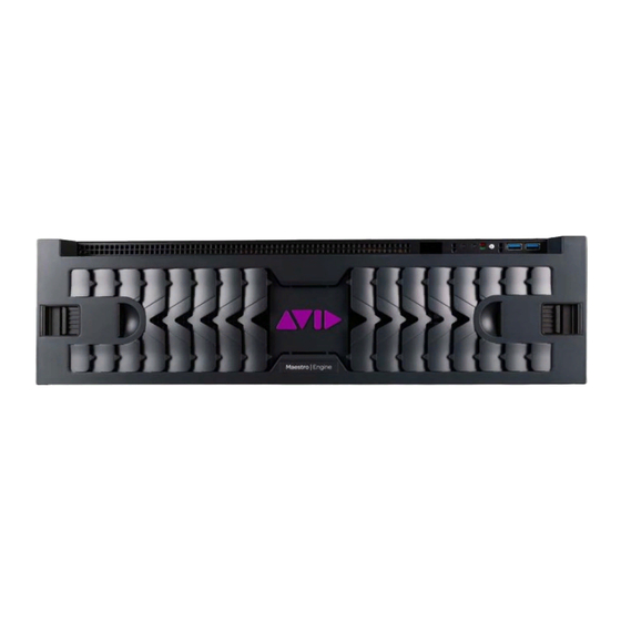
To inspect components for damage: 1. Visually inspect all of the hardware components listed in the previous section to make sure that none of them were damaged during shipment. 2. If you received a hardware component that was damaged, contact Avid Customer Support. Hardware Components Maestro | Engine Front Panel The front of the Maestro | Engine server provides access to the power button, activity LEDs, storage... -
Page 15: Server Front Panel And Led Control Panel
Server Front Panel and LED Control Panel The server has one power button on the top right part of the server. The front panel also contains activity LEDs, storage error LED, and two USB sockets. Server Front View and LED Control Panels The following table describes the LED Control Panels shown in the previous figure. -
Page 16: Avid Maestro | Engine Server - Rear Panel
Avid Maestro | Engine Server - Rear Panel The rear panel of the Maestro | Engine server provides access to the power supplies, 1 gigabit (Gb) Ethernet ports, VGA port, serial port, two USB connectors for the keyboard, mouse. The availability of the Reference IN and Loop sockets, Video Inputs and Outputs depends on the chosen specification. -
Page 17: Power Supplies
Avid Maestro | Engine - Single Channel IP Avid Maestro | Engine - Dual Channel IP Each of these components is described in the topics below. Power Supplies There are two power supplies accessible from the rear of the Maestro | Engine server. If a failure occurs on either one of the power supplies, you can pull the failed power supply out of the server, and install a replacement power supply without turning off the Maestro | Engine server. -
Page 18: Ethernet Ports
Ethernet Ports The Maestro | Engine server is equipped with 2 1GB Ethernet Ports. USB Ports There are two USB ports located on the rear of the Avid Maestro | Engine server. VGA Port There is one VGA port located on the rear of the Avid Maestro | Engine server. -
Page 19: Serial Port
Serial Port There is one Serial port located on the rear of the Avid Maestro | Engine server. Reference There is one Reference input and one Reference loop port located on the rear of the Avid Maestro | Engine server. If the server is the last device in your reference loop, terminate the remaining Ref Loop through a connector with an 75 ohm-rated terminator. -
Page 20: Bypass Board
Bypass Board The bypass board allows you to have a backup feed ready, in case the main feed is disrupted by a power failure. SDI Connections SDI inputs and outputs connectors are linked to Maestro | Engine input and output channels. -
Page 21: Ip Connections
IP Connections IP inputs and outputs connectors are linked to Maestro | Engine input and output channels. -
Page 22: Installing The Server Hardware
Installing the Server Hardware This chapter describes how to install a Maestro | Engine server hardware on your site. Topics in this chapter include: • Electrostatic Discharge Precautions • Installing Maestro | Engine Hardware in a Rack • Installing the Drives in the Server •... -
Page 23: Rack-Mount Requirements
Rack-mount Requirements • Elevated Operating Ambient — If installed in a closed or multi-unit rack assembly, the operating ambient temperature of the rack environment might be greater than room ambient. Therefore, consider installing the equipment in an environment compatible with the maximum ambient temperature (Tma) specified by the manufacturer. -
Page 24: Cabling The Server
When you are installing drives in the Avid Maestro | Engine server, begin the installation at the bottom of a column of drives. Make sure the first drive you install is level and flat as you insert it into the server. Do not force a drive into a slot. -
Page 25: Connecting The Power Cords
Maestro | Engine Server - Rear Panel Connecting the Power Cords Your Maestro | Engine server has two power supplies. If your local power distribution is not compatible with the supplied cords, you must provide your own IEC power cables that are compatible with your country's power system. -
Page 26: Connecting A Keyboard, Monitor, And Mouse
To connect the Ethernet: 1. Your Ethernet switch should be rack mounted. Leave adequate room at the front for cables and at the back for air circulation. 2. Locate Category 5E, 6, or 6A Ethernet cable(s). 3. Attach the other end of the Ethernet cable to suitable port in your switch. Connecting a Keyboard, Monitor, and Mouse You need to provide a standard USB compatible keyboard, monitor and mouse to access the Maestro | Engine server. -
Page 27: Connecting Ip Video Inputs And Outputs
Connecting IP Video Inputs and Outputs The Input/ Output connections vary according to the current settings. To connect IP video output cables on the chassis: 1. Ensure that you have proper fiber cables available. 2. Connect the IP output signal to an outgoing IP output on the server. 3. -
Page 28: Installing The Operating System
Installing The Operating System This topic provides information on how to install the required software system on a Maestro | Engine server. After performing this procedure, you will need to install the RenderEngine, and reconfigure the software settings. The procedures included in this topic should be conducted by Avid Support personnel. Installation Checklist Having your hardware received, the first step to perform is to connect power cables, network cable, VGA monitor and USB keyboard and power the system on, as described in the topic... -
Page 29: Configuring Bios
Configuring BIOS In the event that you need to reimage your Maestro | Engine server, you should first check your BIOS version before installing the CentOS 7 software. If the installed version is older than GRUOV008, update it. If the installed version is correct, configure it as described below. To configure BIOS: 1. -
Page 30: Loading The Centos 7.4 Image On The Server
Loading the CentOS 7.4 Image on the Server Install the CentOS 7 image from the provided bootable drive. Insert the USB drive into one of the USB ports and reboot the server. No additional steps are required during the installation. Before proceeding with the installation, disconnect the clips drives from the motherboard. -
Page 31: Configuring The Server For Your Network
Configuring the Server for Your Network The following topics provide information how to configure the Maestro | Engine server for your network. IP Configuration Open the ifcfg files for each Ethernet port and update the network information there. To assign an IP address: 1. -
Page 32: Installing Kernel
Installing Kernel If your Linux is freshly installed, use the newest available kernel. To install kernel: 1. Download the following file: kernel-3.10.0-693.5.2.el7.Avid.x86_64.rpm 2. Execute the following command: rpm -ivh kernel-3.10.0-693.5.2.el7.Avid.x86_64.rpm 3. Reboot your server. Installing libdvg The next step is to install the latest libdvg middleware. When performing an upgrade of the operating system instead of a clean installation, make sure to remove the previous version of libdvg before installing the newest version. -
Page 33: Verifying The Bus Location Of Uhd2 And Nvidia Cards
Verifying the Bus Location of UHD2 and NVIDIA Cards After installing libdvg, check on which PCI slots the uhd boards and NVIDIA cards are currently configured. To check the NVIDIA and uhd cards bus location on PCI: 1. Verify the location of uhd2 cards by executing the following command: lspci | grep -i orad Check the response: 01:00.0 Bridge: Orad Hi-Tec Systems Device 1980 (rev 11) -
Page 34: Installing The Nvidia Driver
Installing the NVIDIA Driver This topic describes how to install the NVIDIA driver. When performing an upgrade of the operating system instead of a clean installation, make sure to remove the previous versions of the NVIDIA driver before installing the newest version. To install the NVIDIA driver: 1. -
Page 35: Setting Up Raid-10
2. To flash new firmware for domain 1: setenv DVG_DOMAIN 1 dvgflash -board 0 -reconf -list dvgflash -board 0 -write /data/public/gfx_sdi_160_4014.bin -quick To run graphics applications with domains on Maestro | Engine Dual Channel, please note the following: graphics card PCI bus for Domain O is 04:00 and graphics card PCI bus for Domain 1 is 03:00. -
Page 36: Installing Renderengine
3. Edit the /etc/fstab file and add the following line: //WINDOWS_IP/SHAREDDIRECTORY /Control_Data cifs credentials=/etc/ .credentials,rw,uid=1000,gid=1000,nounix,iocharset=utf8,file_mode=0777,dir _mode=0777,sec=ntlm 0 0 4. Mount the Shared Data using the following command: mount /Control_Data If you have a “mount error(13): Permission denied”, you can try to change the sec= parameter to one from the list below: Installing RenderEngine Now, you can install Maestro | RenderEngine for Linux. -
Page 37: Installing Maestro | Engine Manager
5. Select the created host and click Install RenderEngine. 6. Exit the installer. Installing Maestro | Engine Manager The Maestro | Engine Manager (MEM) is a web-based configuration tool that allows to setup your Maestro | Engine machine. To install Maestro | Engine Manager on your Maestro | Engine machine: 1. -
Page 38: Single Channel Configuration
Single Channel Configuration After installing the operating system and RenderEngine on your Maestro | Engine Single Channel machine, the next step is to configure it according to your requirements. Configuring RenderEngine After installing RenderEngine on the required host, configure it as described below. To configure RenderEngine: 1. -
Page 39: Dual Channel Configuration
Dual Channel Configuration After installing the operating system and RenderEngine on your Maestro | Engine Dual Channel machine, the next step is to configure it according to your requirements. Three scenarios are discussed in this topic: • Same Layout and Output Type on Both Domains •... - Page 40 Then, open the RE.xml file to set the required layout and enable CPU cores logging. To edit the RE.xml file: Open the /data/RE/bin/RE.xml file and set the desired layout. <Layout ConfigPathName="Layout.xml" DetectName="No" Name="HDWithAlpha" Log="Yes" AutoReactivateScenes="No" /> Enable CPU cores logging. <Cores ConfigPathName="Cores.xml"...
-
Page 41: Configuring Maestro | Engine Manager
</VL-AudioMixerThread> <AudioMixer> <Priority Type="Realtime" Level="100"/> <Affinity Value="2,3"/> </AudioMixer> <TimecodeProviderThread> <Priority Type="Realtime" Level="100"/> <Affinity Value="2,3"/> </TimecodeProviderThread> </Config> Configuring Maestro | Engine Manager The Maestro | Engine Manager is a web-based configuration tool that allows to setup your Maestro | Engine machine. Install the Maestro | Engine Manager as described in the Installing Maestro | Engine Manager topic. -
Page 42: Starting Renderengine
Starting RenderEngine After applying the configuration, you can start RenderEngine on both domains. To start RenderEngine: Use the following commands: cd /data/RE/bin ./start.sh domain=0 ./start.sh domain=1 - or - Login to Maestro | Engine Manager of your machine, and start RenderEngine using the bottom panel buttons. - Page 43 Domain 1...
-
Page 44: Different Layout And Output Type On Both Domains
Different Layout and Output Type on Both Domains In this scenario, different layouts and output types are going to be implemented on both domains. Begin the configuration by changing the RenderEngine configuration. Configuring RenderEngine First, open the /data/RE/bin/start.sh script file to change the gfx_busses indexes and add supplementary variables responsible for multithread decoding for clip player and audio insertions. - Page 45 To edit the RE.xml file: Open the /data/RE/bin/RE.xml file: a. Set the desired layout for domain 0 and domain 1. <Layout ConfigPathName="Layout.xml" DetectName="No" Name="HD" NameDomain0="HDWithAlpha" NameDomain1="PALWithAlpha" Log="Yes" AutoReactivateScenes="No" /> b. Define different HdvgCpProfiles.xml files for both domains. <Dvg ConfigPathName="/Control_Data/config/HdvgCpProfile.xml" ConfigPathNameDomain0="/Control_Data/config/HdvgCpProfileHD.xml" ConfigPathNameDomain1="/Control_Data/config/HdvgCpProfileSD.xml"...
-
Page 46: Configuring Maestro | Engine Manager
To edit the Cores.xml file: Open the /data/RE/bin/Cores.xml file and in the <SingleGPU> section change the Affinity Value to “2,3” for each thread as presented below: <SingleGPU> <Config HyperThreading="Yes,No" CoresCount="4-16"> <DefaultPriority Type="Normal"/> <DefaultAffinity Value="1,4-16"/> <MainThread> <Priority Type="Realtime" Level="100"/> <Affinity Value="2,3"/> </MainThread>... -
Page 47: Starting Renderengine
There should only be two additional files in the G:\config folder, except for the default configuration file. Starting RenderEngine After applying the configuration, you can start RenderEngine on both domains. To start RenderEngine: Use the following commands: cd /data/RE/bin ./start.sh domain=0 ./start.sh domain=1 - or - Login to Maestro | Engine Manager of your machine, and start RenderEngine using the bottom... - Page 48 Domain 0...
- Page 49 Domain 1...
-
Page 50: Mixing
Mixing In this scenario, mixing of graphic with video signal is enabled. To enable mixing: 1. Login to Maestro | Engine Manager by opening a web browser and entering the Maestro | Engine unit’s IP address as the URL, with the suffix 8080. For example, 192.0.2.0:8080. 2. -
Page 51: Appendix A Safety And Regulatory Information
Safety and Regulatory Information This document contains safety and regulatory information for Avid Maestro | Engine hardware. Important Safety Instructions 1. Read these instructions. 2. Keep these instructions. 3. Heed all warnings. 4. Follow all instructions. 5. Do not use this equipment near water. 6. -
Page 52: Rack-Mount Requirements
17. The equipment shall be used at a maximum ambient temperature of 40° C. 18. This unit may be provided with a power supply cord set suitable for 120V AC input only (for U.S.A.and Canada). For other than U.S.A. and Canada, a qualified person must provide for use with this unit, an appropriate, approved power supply cord set which is in compliance with the end use country requirements and has a minimum cross-sectional area of 1.0mm2. -
Page 53: Fcc Notice
• EN55103-1 E4 • EN55024 • EN55103-2 E4 • AS/NZS CISPR 32 Class A • CISPR32 Class A • VCCI Class A • IEC/EN/UL60950-1 • CAN/CSA-C22.2 No. 60950-1-07 This equipment has been tested to comply with USA and Canadian safety certification in accordance with the specifications of UL Standards: IEC/UL60950-1 and Canadian CAN/CSA-C22.2 No. - Page 54 Cet appareil numérique de la classe A respecte toutes les exigences du R?glement sur le matériel brouilleur du Canada. Australian Compliance Environmental Compliance Disposal of Waste Equipment by Users in the European Union This symbol on the product or its packaging indicates that this product must not be disposed of with other waste.
Need help?
Do you have a question about the Maestro/Engine and is the answer not in the manual?
Questions and answers