Table of Contents

Related Manuals for Avid Technology AS3000


Summary of Contents for Avid Technology AS3000
- Page 1 ® Avid AS3000 Setup Guide...
-
Page 2: Legal Notices
This document is supplied as a guide for Avid AS3000 server. Reasonable care has been taken in preparing the information it contains. - Page 3 Redistribution and use in source and binary forms are permitted provided that the above copyright notice and this paragraph are duplicated in all such forms and that any documentation, advertising materials, and other materials related to such distribution and use acknowledge that the software was developed by the University of California, Berkeley. The name of the University may not be used to endorse or promote products derived from this software without specific prior written permission.
- Page 4 The following disclaimer is required by Interplay Entertainment Corp.: The “Interplay” name is used with the permission of Interplay Entertainment Corp., which bears no responsibility for Avid products. This product includes portions of the Alloy Look & Feel software from Incors GmbH.
- Page 5 Microsoft Corporation in the United States and/or other countries. All other trademarks contained herein are the property of their respective owners. Avid AS3000 Setup Guide • 013030652-01 Rev. A • February 2011 • Created 4/18/11...
-
Page 6: Table Of Contents
Avid AS3000 Front Panel and LEDs ....... . . 12... - Page 7 Replacing System Drives in the AS3000 ....... . . 38...
- Page 8 European Union Declaration of Conformity ....... 74 Disposal of Waste Equipment by Users in the European Union ....76 Argentina Conformity .
-
Page 9: Using This Guide
It is designed for media facilities and broadcasters, delivering stable operation and class-leading value. This document describes the basic features for all Avid AS3000 models. Therefore, your system might not contain certain features that are covered in the documentation. See your Avid product documentation for details about installing software and PCIe cards. -
Page 10: If You Need Help
To view the online versions, visit the Knowledge Base at www.avid.com/US/support. 3. Check the documentation that came with your Avid application or your hardware for maintenance or hardware-related issues. 4. Visit the online Knowledge Base at www.avid.com/US/support. Online services are available 24 hours per day, 7 days per week. -
Page 11: As3000 Overview
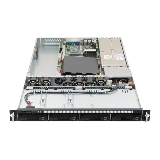
1 Gb) Ethernet ports, two PCI Express x8 slots, plus redundant power and fans. AS3000 Hardware The Avid AS3000 is a standalone system that runs the application software for a number of ® Avid systems. It is a single or dual-processor, rack-mount, Windows computer that contains two 1 TB drives for storing data. -
Page 12: Avid As3000 Front Panel And Leds
1 AS3000 Overview Avid AS3000 Front Panel and LEDs The front of the AS3000 provides access to 4 drive carriers, a USB port, network port activity LEDs, disk activity LED, an error LED, a system ID button, and Power and Reset buttons. - Page 13 The number beside the LED corresponds with the number beside the Gb Ethernet port on the rear of the enclosure. For example, Connector 1 is LED 1 on the front. See “AS3000 Rear Panel” on page Red System error LED Illuminates red when an error is detected with the system (fan, power supply, temperature, voltage).
-
Page 14: As3000 Rear Panel
1 AS3000 Overview AS3000 Rear Panel The AS3000 rear panel provides access to the power supplies, video monitor port, four 1 Gigabit (Gb) Ethernet connectors, serial connector, expansion slots, and two USB connectors for the application key, and keyboard or mouse. -
Page 15: System Drives
System Drives in the AS3000” on page Power Supplies There are two power supplies accessible from the rear of the AS3000 enclosure. If a failure occurs on either one of the power supplies, you can pull the failed power supply out of the enclosure and install a replacement power supply without turning off the AS3000 enclosure. - Page 16 1 AS3000 Overview...
-
Page 17: Installing The As3000 System
Installing the AS3000 System This chapter describes how to install the AS3000 server. The server can be standalone or connected to an in-house network. Topics in this chapter include: • Avid AS3000 Server • Installing AS3000 Hardware in a Rack •... -
Page 18: Avid As3000 Server
Optional line cards will require appropriate cables. See “Supported Cabling” on page Keep the accessories that ship in the AS3000. You might need them later for installing optional disk drives or installing the server in a rack. Keep the shipping boxes that come with your AS3000 hardware. You might need to... -
Page 19: Installing As3000 Hardware In A Rack
To ensure the stability of the rack enclosure, start from the bottom when you install the rack components in the rack enclosure. The AS3000 has vent holes on the top of the enclosure. Avid has performed thermal testing with the top vent holes blocked, and the results indicated that even with the top vent holes... -
Page 20: Rack-Mount Requirements
Avid AS3000 airflow is from the front of the enclosure to the rear. Make allowances for cooling air to be available to the front panel surface and no restrictions at the rear. -
Page 21: Separating The Slide Rails
Installing AS3000 Hardware in a Rack Separating the Slide Rails You need to separate the slide rails and attach the inner “movable” section to the AS3000 and the outer “fixed” section to the rack rails. To separate the slide rails: 1. -
Page 22: Attaching Inner Slide Rails To The Avid As3000 Server
2 Installing the AS3000 System Attaching Inner Slide Rails to the Avid AS3000 Server Attach the inner slide rails that were separated from the outer slide rails to the AS3000. To attach the inner slide rails: 1. Position the inner slide rail against the side of the server so that the spring clip end is toward the rear of the server. - Page 23 Installing AS3000 Hardware in a Rack Positioning the Outer Slide Rail with the Front Rack-Mounting Rail 2. Push the outer slide rail bracket assembly through the holes in the front of the vertical mounting rail of the rack. 3. Push the outer side towards the outside of the rack and make sure that the black plastic retainers are in the hole.
- Page 24 2 Installing the AS3000 System Outer Slide Rail Attached to the Front Rack-Mounting Rail 4. Adjust the outer slide rail bracket assembly to the rear mounting rail. 5. Install the rear outer slide rail bracket assembly in the rear mounting rail as you did for the front rack-mounting rail.
-
Page 25: Attaching The Outer Rails To A Round-Hole Rack
“Attaching the Outer Rails to a Square-Hole Rack” on page To attach the outer slide rails to a round hole rack: 1. Select a position in the rack where the AS3000 is at the proper baseline position. Positioning the Avid AS3000 server in a round hole rack... - Page 26 2 Installing the AS3000 System Attaching the Round Hole Adapter to the Bracket Assembly Outer slide rail bracket assembly Bracket assembly tabs Round hole adapter 3. With the bracket assembly tabs aligning with the cut-out in the round hole adapter, swing the adapter so that the holes face the front of the bracket assembly as shown in the following illustration.
- Page 27 Installing AS3000 Hardware in a Rack Insert the Outer Slide Rail to the Front Rack-Mounting Rail 5. Insert the small-short Phillips-head screws through the round-hole adapter and mounting rail, into the bracket. The small screws that ship with the round hole adapters are 10-32 screws.
-
Page 28: Securing The Avid As3000 Server In A Rack
2. Push the front of the Avid AS3000 server flush against the front mounting rail. The holes in the server front panel align with the holes in the front mounting rail. -
Page 29: Installing And Removing The Front Bezel
2. Turn each key clockwise for a quarter turn. 3. Place the bezel, with the Avid logo on the left, over the handles of the rackmount ears. 4. Lock the bezel in place by turning the keys counterclockwise for a quarter turn. -
Page 30: Connecting Power Cords
Do not place the monitor on top of the AS3000. 2. Attach the VGA connector on the monitor cable to the 15-pin video port on the back of the AS3000. Secure the connector with the thumbscrews on the connector. For exact locations see “AS3000 Rear Panel”... -
Page 31: Connecting To An Ethernet Network
Connecting to an Ethernet Network Connecting to an Ethernet Network You can connect the AS3000 to an Ethernet network using the four 1 Gb Ethernet ports on the rear of the enclosure. Please note that some Avid applications require the use of one or both of the PRO/1000 PT ports (Ports 2 and 4). - Page 32 2 Installing the AS3000 System...
-
Page 33: Customizing The Server Operating System
Customizing the Server Operating System This chapter describes Windows operating system parameters that need setting on the Avid AS3000. Topics in this chapter include: • Windows Operating System and Settings • Copying the Product Recovery Image to the USB Flash Drive •... -
Page 34: Windows Operating System And Settings
“Product Recovery” on page When turning on your Avid AS3000 for the first time the Apply Computer Setup message is displayed for 3 to 5 minutes. Use the information in the following sections to configure the Avid AS3000 with the correct date and time, computer name, and network properties. -
Page 35: Specifying A Unique Computer Name
3. In the Computer Name tab, click the Change button. 4. Type the new name of the Avid AS3000 in the Computer name text box. 5. (Option) Determine if you need to select the Domain or Workgroup in the “Workgroup”... -
Page 36: Loading Application Software
3 Customizing the Server Operating System Loading Application Software The Avid AS3000 does not have a DVD reader. Software is loaded onto the system using a USB flash drive. Use the application software flash drive(s) to install your Avid application software such as Interplay Engine or Interplay Capture. -
Page 37: Adding And Replacing Hardware
Adding and Replacing Hardware This chapter provides procedures for adding and replacing components in your Avid AS3000. Do not add any hardware if there are any issues with the system. Correct all problems before adding new hardware and making changes to the system. Perform a quick check to verify that the system is in good working order. -
Page 38: Replacing System Drives In The As3000
System drive (ID 1) The two drives are mirrored and are accessible from the front of the AS3000. If you have a failure on either one of the two system drives you can pull the failed drive out of the server and install a replacement without turning off the server. - Page 39 Replacing System Drives in the AS3000 Intel Rapid Storage Technology Application A. Run hardware scan button B. Disk icons C. Status line 3. Pull the failed drive out of the server and install a replacement without turning off the server.
-
Page 40: Locking And Unlocking A Drive
“Configuring the System Drive Using Windows Setup” on page 8. Reinstall the application software. Locking and Unlocking a Drive Avid recommends that you keep the drives locked in the enclosure. The AS3000 ships with several drive keys. To lock a drive: 1. -
Page 41: Removing And Installing A Hot-Swap Hard Drive
This section describes a generic procedure for installing or replacing hot-swap hard drives on the AS3000. For additional information, see “Replacing System Drives in the AS3000” on page To removing and install a hot-swap hard disk drive: 1. If necessary, remove the front bezel. See “Installing and Removing the Front Bezel”... - Page 42 Removing and Installing a Hot-swap Hard Drive 4. Pull out on the black lever and slide the carrier from the server system. Removing the Hot-swap Drive Carrier from the Server System A. Latch button and black lever 5. If you are installing a drive in an empty drive carrier, proceed to Step 8. 6.
- Page 43 Make sure that the SATA connector is not blocked by the metal tray. If you are installing a drive for the first time, use the screws that were included in the AS3000 accessory kit. See “Avid AS3000 Server”...
- Page 44 Removing and Installing a Hot-swap Hard Drive The following illustration shows the connectors on the bottom of the drive carrier. Bottom View of Drive Attached to Drive Carrier A. Drive connector B. Screws C. Latch 11. With the black lever in the fully open position, slide the drive assembly into the server system.
-
Page 45: Removing And Installing The System Cover
12. When the black drive carrier lever begins to close by itself, push on it to lock the drive assembly into place. This seats the drive in the AS3000. You’ll hear a click when the drive is fully seated and the lever latches in place. -
Page 46: Installing And Removing A Pcie Add-In Card
Installing and Removing a PCIe Add-in Card 3. Disconnect the AC power cords. 4. Unscrew the thumbscrews at the back of the unit until they are loose. 5. Pull the thumbscrews backwards and slide the cover until the tabs disengage from the front of the unit. - Page 47 Installing and Removing a PCIe Add-in Card 3. Remove the server system cover. For instructions, see “Removing and Installing the System Cover” on page 4. Disconnect any cables attached to any add-in cards. 5. If the PCIe card is a full-height card, remove the lateral movement support by removing the two screws connecting it to the chassis.
- Page 48 B. Bezel retainer 7. Remove both filler panels. When adding the first PCIe card, Avid recommends that you add it to the bottom slot unless the Avid system requires the card to be in a designated slot. See your product specific documentation for details.
- Page 49 Installing and Removing a PCIe Add-in Card The following illustration shows the card installed in the bottom slot. Adding a Card to the Bottom Slot A. Bottom slot...
- Page 50 Installing and Removing a PCIe Add-in Card 9. Replace the top filler panel and attach the bezel retainer with two screws as shown in the following illustration. Replacing the Top Filler Panel and the Bezel Retainer A. Top filler panel B.
-
Page 51: Removing And Installing The Processor Air Duct
Removing and Installing the Processor Air Duct Removing and Installing the Processor Air Duct The following illustration shows the processor air duct. You must remove the processor air duct in order to add or remove memory. Processor Air Duct A. Processor air duct Always operate your server system with the processor air duct in place. - Page 52 Removing and Installing the Processor Air Duct 4. Loosen the three screws holding the processor air duct tabs to the chassis. Removing the Processor Air Duct A. Processor air duct screws 5. (Option) Leave the completely loosened screws sitting on the tabs. Then you can lift the processor air duct and the screws out of the chassis at the same time.
-
Page 53: Installing And Removing Memory
A. Memory for Processor CPU 0 B. Memory for Processor CPU 1 The AS3000 ships from the factory with three 2 GB DDR-3 DIMMs per processor. The AS3000 has three memory channels per processor and two DIMMs per memory channel.The following illustration shows the AS3000 channel and DIMM locations. Channels on Processor CPU 0 increment from left to right and channels on Processor CPU 1 increment from right to left. - Page 54 • Install equal sized DIMMs per channel. • Use only registered DDR-3 memory as recommended by Avid for applications that require additional memory. • If you are only using three DIMMs, install one per channel in the DIMM 0 position of each...
- Page 55 Installing and Removing Memory To install DIMMs: 1. Observe the safety precautions described in “Electrostatic Discharge Precautions” on page 37 “Safety and Regulatory Information” on page 2. Power down the server and unplug all peripheral devices and the AC power cables. 3.
-
Page 56: Replacing A Power Supply
Replacing a Power Supply The AS3000 is designed to run with two operating power supplies. A power supply can be replaced if it fails. If a power supply fails, the LED on the power supply and the front panel LED turn red and a beeping alarm sounds. - Page 57 4. Insert the replacement power supply module into the power supply cage until it clicks into place. 5. Reconnect all peripheral devices and the AC power cords into the server. Note that the AS3000 will power up without having to turn on the power switch.
-
Page 58: Chapter 5 Product Recovery
You might need to reinstall the Windows operating system on your server if you are directed to do so by Avid Customer Support or if you are initializing a new drive. Perform an installation to the entire system (C:, D:, and E:). This replaces all the data from all the available partitions on your system drive. -
Page 59: Locating The Recovery Image
16 GB USB flash drive provided with your AS3000. When you perform a full product recovery of the Avid AS3000 system drive, you lose the product recovery image and data on the D: partition of the system drive. - Page 60 Creating a Product Recovery USB Flash Drive 2. Locate the 16 GB USB flash drive Avid provided with the Avid AS3000 and insert it into the front USB port. 3. Double-click the AvidRecoveryImageTool.exe file. The Avid USB recovery image creator window opens.
-
Page 61: Reinstalling The Windows Operating System
To reinstall the Windows operating system from the Avid Product Recovery flash drive: 1. Locate the 16 GB USB flash drive with the Avid AS3000 image. 2. If necessary, stop your Avid application software. See your product documentation for details. - Page 62 Volume.” Depending on the manufacturer of the USB flash drive, this USB selection in the BIOS might change. The AS3000 includes a Kingston USB flash drive. This might not be the manufacturer of the USB flash drive in future releases.
-
Page 63: Configuring The System Drive Using Windows Setup
The Product Key Authenticity is verified with Microsoft through an Internet connection. If you do not have the Avid AS3000 connected to the internet, you need to phone in your Product Key and get an Authenticity number back from Microsoft. The phone number appears on the screen. - Page 64 If you have changed the computer host name of your server, you need to reapply your computer host name again. 7. Start the system and install your Avid application software, see “Loading Application Software” on page...
- Page 65 5 Product Recovery...
-
Page 66: Specifications And Notices
Component Dimensions and Weight Component Height Width Depth Weight Avid AS3000 server 1.75 in (44.4 mm) 19 in (482.6 mm) 27 in (685.8 mm) 40.0 lb (18.1 kg) with drives installed Environment The following table lists the environmental specifications. Environmental Specifications Operating... -
Page 67: Electrical
Avid AS3000 hardware. If you do not create a separately derived power system, you need to make sure the power outlets you use are from the same distribution panel. -
Page 68: Uninterruptible Power Supply (Ups)
Windows server to send alerts to other Windows servers to perform actions. If your Avid AS3000 server is connected to a network, network policy settings might also prevent you from completing this procedure. Make sure there is adequate power and the correct receptacle type for each hardware component, the rack power strips, and the UPSes. -
Page 69: Supported Cabling
Specifications and Notices Supported Cabling Avid supports the following cable types for connecting an Avid AS3000 server system. For cabling information for specific products, see your Avid product documentation. If you need to run your cable greater distances, call Avid Customer Support for supported cable and accessory information. -
Page 70: Appendix A Safety And Regulatory Information
Operate the device within its marked electrical ratings and product usage instructions. If you need to replace a battery in an Avid hardware unit, be sure to use the correct battery type. There might be a risk of explosion if a battery is replaced by an incorrect... -
Page 71: Fcc Notice
A Safety and Regulatory Information (Hebrew Warnings and Cautions) FCC Notice Part 15 of the Federal Communication Commission Rules and Regulations has established Radio Frequency (RF) emission limits to provide an interference free radio frequency spectrum. Many electronic devices produce RF energy incidental to their intended purpose. Class A Equipment This equipment has been tested and found to comply with the limits for a Class A digital device, pursuant to Part 15 of the FCC rules. -
Page 72: Modifications
Avid AS3000 airflow is from the front of the enclosure to the rear. Make allowances for cooling air to be available to the front panel surface and no restrictions at the rear. -
Page 73: Led Safety Notices
A Safety and Regulatory Information Make sure your rack enclosure is stable enough to prevent tipping over when one or more Avid AS3000 servers are extended on the sliding rails. • Circuit Overloading — Consideration should be given to the connection of the equipment to the supply circuit and the effect that overloading of the circuits might have on overcurrent protection and supply wiring. -
Page 74: European Union Declaration Of Conformity
European Union Declaration of Conformity Avid hardware might contain LED or Laser devices for communication use. These devices are compliant with the requirements for Class 1 LED and Laser Products and are safe in the intended use. In normal operation the output of these laser devices does not exceed the exposure limit of the eye and cannot cause harm. - Page 75 A Safety and Regulatory Information European Contact: Nearest Avid Sales and Service Office or Avid Technology International B.V. Sandyford Industrial Estate Unit 38, Carmanhall Road Dublin 18, Ireland declare under our sole responsibility that the product, erklären, in alleniniger Verantwortung,daß dieses Produkt, déclarons sous notre seule responsabilité...
-
Page 76: Disposal Of Waste Equipment By Users In The European Union
Disposal of Waste Equipment by Users in the European Union EN55022:2006 /A1:2007 EN55024:1998 /A1:2001 /A2:2003 EN61000-3-2:2006 EN60000-3-3:1995 /A1:2001 /A2:2005 Gerrett Durling, VP of Engineering, Shared Services Issued In Burlington MA, USA 2011 Disposal of Waste Equipment by Users in the European Union This symbol on the product or its packaging indicates that this product must not be disposed of with other waste. -
Page 77: Japan Emc Regulations
A Safety and Regulatory Information Ken Hopkins Avid Technology (Aust) Pty Ltd c/o – Elliot House Suite 810, Level 8 140 Arther St North Sydney NSW – 2060 Japan EMC Regulations Class A Equipment This is a Class A product. In a domestic environment this product may cause radio interference in which case the user may be required to take corrective actions. -
Page 78: Taiwan Emc Regulations
Taiwan EMC Regulations Taiwan EMC Regulations Taiwan EMC Regulations BSMI Class A EMC Warning Warning Statement 1. UV ray radiation Following statement or equivalent: Following marking or other equivalent marking: 2. Operator touchable area protection Operation manual should have following statement and statement should be shown on device, or put on similar sentence: 3. - Page 79 A Safety and Regulatory Information Injury may result from high temperatures under normal operating conditions, causing: Burns due to contact with hot accessible parts Degradation of insulation and of safety-critical components Ignition of flammable liquids Examples of measures to reduce risks include: Taking steps to avoid high temperature of accessible parts Avoiding temperatures above the ignition point of liquids Provision of marking to warn USERS where access to hot parts is unavoidable...
- Page 80 Taiwan EMC Regulations Examples are sonic (acoustic), radio frequency, infra-red, ultraviolet and ionizing radiation, and high intensity visible and coherent light (lasers). Examples of measures to reduce risks include: Limiting the energy level of potential radiation sources Screening radiation sources Provision of SAFETY INTERLOCKS Provision of markings to warn USERS where exposure to the radiation hazard is unavoidable...
- Page 81 A Safety and Regulatory Information 10. Replaceable batteries If an equipment is provided with a replaceable battery, and if replacement by an incorrect type could result in an explosion (for example, with some lithium batteries), the following applies: If the battery is placed in an OPERATOR ACCESS AREA, there shall be a marking close to the battery or a statement in both the operating and the servicing instructions If the battery is placed elsewhere in the equipment, there shall be a marking close to...
- Page 82 Taiwan EMC Regulations 11. Warning to service persons Suitable markings shall be provided on the equipment or a statement shall be provided in the servicing instructions to alert a SERVICE PERSON to a possible hazard, where both of the following conditions exist: Where a fuse is used in the neutral of single-phase equipment either permanently connected or provided with a non-reversible plug Where, after operation of the fuse, parts of the equipment that remain energized...
- Page 83 Avid Technical Support (USA) Product Information 75 Network Drive Visit the Online Support Center at For company and product information, Burlington, MA 01803-2756 USA www.avid.com/support visit us on the web at www.avid.com...
Need help?
Do you have a question about the AS3000 and is the answer not in the manual?
Questions and answers