Table of Contents
Advertisement
Advertisement
Table of Contents

Related Manuals for Avid Technology NEXIS PRO 20TB


Summary of Contents for Avid Technology NEXIS PRO 20TB
- Page 1 ® Avid NEXIS Setup and Maintenance Guide December 2019...
- Page 2 This guide is protected by copyright. This guide is for your personal use and may not be reproduced or distributed, in whole or in part, without permission of Avid. Reasonable care has been taken in preparing this guide; however, it may contain omissions, technical inaccuracies, or typographical errors. Avid Technology, Inc. disclaims liability for all losses incurred through the use of this document.
- Page 3 Mbox, MediaCentral, Media Composer, NewsCutter, Pro Tools, ProSet and RealSet, Maestro, PlayMaker, Sibelius, Symphony, and all related product names and logos, are registered or unregistered trademarks of Avid Technology, Inc. in the United States and/or other countries. The Interplay name is used with the permission of the Interplay Entertainment Corp.
-
Page 4: Table Of Contents
Contents Using This Guide ....................vii Symbols and Conventions. - Page 5 Chapter 4 Adding and Replacing Hardware ..............49 Collecting Logs for Customer Care .
- Page 6 Class B Equipment ................69 LED Safety Notices .
-
Page 7: Using This Guide
Using This Guide ® The Avid NEXIS media network provides a high-performance distributed file system that contains ® high-capacity shared media storage for workgroups of connected Avid editing workstations. Symbols and Conventions Avid documentation uses the following symbols and conventions: Symbol or Convention Meaning or Action A note provides important related information, reminders, recommendations, and strong suggestions. -
Page 8: If You Need Help
If You Need Help If You Need Help If you are having trouble using your Avid product: 1. Retry the action, carefully following the instructions given for that task in this guide. It is especially important to check each step of your workflow. 2. -
Page 9: Avid Nexis System Overview
Avid NEXIS System Overview The Avid NEXIS system is a shared storage solution for acquisition, creative, distribution, and archive media workflows. Avid network storage systems are built for media and entertainment. They enable multiple clients to share, capture, play, and edit video and audio media. Clients access Avid NEXIS systems through external switch connections. -
Page 10: Supported Configurations
Supported Configurations Model Size Features System Director Appliance Server built from common hardware modules as other Avid NEXIS products. (System Director Appliance) Contains one or two Controllers, two 764W power supply/cooling modules, and two solid state system drives. The System Director Appliance does not provide media storage; the unused drive slots are covered with blank plates. -
Page 11: System Details
System Details Configurations with an External System Director (System Director Appliance) The System Director Appliance runs the System Director (but does not provide media storage) for configurations that exceed the limits of the embedded System Director. The System Director Appliance uses either the Avid NEXIS | FS Extended license or the Avid NEXIS | FS Advanced license, depending on how many Media Packs or clients you want to manage. -
Page 12: Engine And Sda Serial Number Location
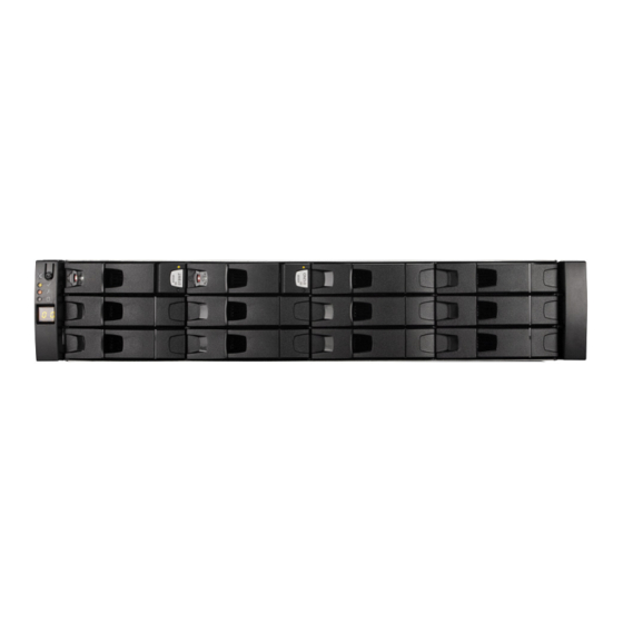
System Details Engine and SDA Serial Number Location On all Avid NEXIS Engines (Enterprise and PRO) and the System Director Appliance, the chassis serial number is printed on a label attached to the left rear chassis mounting ear. The following figure shows the location of the serial number label. - Page 13 System Details 2U Chassis Front Views and Details The front of all 2U chassis has a removable bezel (not shown). Removing the bezel allows access to the drive slots. The Avid NEXIS | E2, Avid NEXIS | E2 SSD, and Avid NEXIS | PRO systems support one Media Pack (10 drives) for media storage and two system drives.
- Page 14 System Details Avid NEXIS | PRO with 2TB SAS Drives In an Avid NEXIS | PRO with a Media Pack of 2TB SAS drives, the Controller is located in slot 0 (top), as shown. this type of Controller has no identification label, and the Host Fabric section is purple.
-
Page 15: 4U Chassis Details
System Details Avid NEXIS | PRO with Controller 10 in Slot 1 (for 4TB SATA Drives) Rear View Features of 2U Chassis Component Notes Power Supply/Cooling Modules 764W power supply and cooling fan modules. (PCM) The left power supply is numbered 0, the right is numbered 1, in event and error messages. - Page 16 System Details 4U Chassis Rear View and Details The rear of the Avid NEXIS | E4 provides access to the Controllers and the PCMs. If you use a redundant Controller, it must be installed in the third slot from the top (slot 2), as shown. Rear View Features of Avid NEXIS | E4 Component Notes...
-
Page 17: 5U Chassis Details
System Details Control Panel for all 2U and 4U Chassis The following figure shows the control panel on the left side of the chassis on all of the following: • Avid NEXIS | E2 • Avid NEXIS | E2 SSD •... - Page 18 System Details 5U Chassis Front View and Details On 5U chassis, the bezels are attached at the factory and do not need to be removed for any system maintenance procedures. The 5U chassis has two drive drawers, each holding 42 drives. The front of the chassis has two status panels, as described below and shown in the following figure: •...
- Page 19 System Details Description Status/Purpose Power On/Standby Green when system is on (operational). Amber when system is in standby mode (not operational). Module Fault indicator Amber when there is a system hardware fault. In that case, another LED on the faulty component may be lit. Logical Status indicator When lit, indicates that a drive has failed.
- Page 20 System Details Description Status/Purpose Activity bar graph Shows the amount of data I/O from zero segments lit (no I/O) to all six segments lit (maximum I/O) 5U Chassis Drive Slot Numbering The Avid NEXIS | E5 and Avid NEXIS | E5 NL has two drawers for the system and Media Pack drives.
-
Page 21: Types Of Controllers
Types of Controllers Component Notes Controller 0, If only one controller is present, it is typically in the left slot. Controllers are identified in Controller 1 error and status messages as 0 (left) and 1 (right). If a second Controller is installed, it is identified as Controller 1. Avid NEXIS | E5 NL comes with a QSFP to SFP+ adapter to connect 10GbE SFP+ optics or cables to a switch. - Page 22 Types of Controllers Used in and Supported Controller Type (Label) Technical Details Slots Avid NEXIS PRO 40 G2/E2 G2 Six cores with 32GB memory / USM version Avid NEXIS | PRO 40TB 1.37 factory installed / Supports a 10GbE switch Slot 1 (bottom) only, upside connection down...
- Page 23 Types of Controllers Used in and Supported Controller Type (Label) Technical Details Slots Controller E5 NL Twelve cores with 128GB memory / Supports a Avid NEXIS | E5 NL 10GbE switch connection Both slots (left and right) Avid NEXIS E5 NL G2 Twelve cores with 128GB memory / USM Avid NEXIS | E5 NL version 1.37 factory installed / Supports a 10GbE...
- Page 24 Types of Controllers Component Notes POST LEDs (Shown for reference only.) Serial Port (Shown for reference only. Not used) Management Interface 1GbE port for connecting the Controller to a laptop or other computer to install the Port (left port only) Avid NEXIS software and initially configure the system.
-
Page 25: Controller Functionality And Restrictions
Controller Functionality and Restrictions Avid NEXIS E-Series Controller Features Description Purpose Management Interface port, The Management Interface port is used to connect to a laptop or other computer to install the Avid NEXIS software and initially configure the system. Default IP Interconnect Interface port address is 169.254.10.10. -
Page 26: System Director Functionality
System Director Functionality Both Controllers are active at the same time; there is no Active and Standby designation. If one entire Controller fails, the System Director service (and other services) can fail over to the other one while the system keeps running. However, failover does not occur if the network connection to a Controller fails. -
Page 27: Media Pack And System Drives
Media Pack and System Drives System Directors, workgroup servers, and clients must all be synchronized with a common time of day. For information on setting the Network Time Protocol (NTP), see “Software Installation and System Setup” on page Media Pack and System Drives A Media Pack is a set of 10 drives, all of which are the same capacity and type. - Page 28 Media Pack and System Drives The System Director, whether running on an Engine or in the System Director Appliance, uses the system drives for metadata, startup files, and other system files. The Engine or System Director Appliance can run with one failed system drive. Avid recommends replacing it as soon as possible. Typically, the system drives occupy slots 0 and 1 in the System Director Appliance and all Engines except the Avid NEXIS | E5 and Avid NEXIS | E5 NL, and the Media Pack drives use the remaining slots.
- Page 29 Media Pack and System Drives The drives used in the 2U and 4U chassis and System Director Appliance have a lock indicator and two LEDs that show the drive status, explained in the following figure and table. 2U and 4U Drive Features Feature Status Indicator Power and activity LED...
-
Page 30: Power Supplies
Power Supplies Leave failed drives in place until you have a replacement so you maintain the proper airflow. Obtain a replacement as soon as possible. Power Supplies Depending on your Avid NEXIS model, the Engine or System Director Appliance has the following number and type of power supply/cooling modules (PCMs) or power supply units (PSUs): •... - Page 31 Power Supplies 764W PCM (All 2U Chassis including System Director Appliance) The bottom two LEDs, marked with battery icons, are not used.
- Page 32 Power Supplies 580W PCM (Avid NEXIS | E4) The LEDs on the 580W PCM work together to indicate overall module status; in the following table, for each row, all the LEDs must be in the listed state for the definition to apply. 580W Power Supply LED States AC Fault Fan Fault...
- Page 33 Power Supplies 2200W PSU (Avid NEXIS | E5 and Avid NEXIS | E5 NL) 2200W PSU Details 2200W PSU LED Status PSU Fail AC Fail Power OK (Amber) (Amber) (Green) Status No AC power to either PSU PSU present but not supplying power Mains AC present, switch on.
- Page 34 Power Supplies 2200W PSU LED Status PSU Fail AC Fail Power OK (Amber) (Amber) (Green) Status PSU alert state (usually due to reaching critical temperature) Mains AC to this PSU is missing (This PSU is on standby, other PSU is OK) GEM software has lost communication with PSU PSU has failed Avid NEXIS | E5 and Avid NEXIS | E5 NL Fans...
- Page 35 Power Supplies Leave failed power supply or cooling modules in place until you have a replacement so you maintain the proper airflow. Obtain a replacement as soon as possible.
-
Page 36: Connecting The Equipment
Connecting the Equipment This chapter explains how to rack mount and connect the system hardware. Rack Mounting Guidelines and Requirements Avid recommends installing the Avid NEXIS hardware in a rack, using the following guidelines: • If installed in a closed or multi-unit rack assembly, the operating ambient temperature of the rack environment might be greater than room ambient. - Page 37 Mounting the Engine or System Director Appliance Rack Units Avid NEXIS Model Needed Avid NEXIS | E4 Avid NEXIS | E5, Avid NEXIS | E5 NL The rack mount kit can accommodate racks with round, square, or threaded holes, sometimes called broadcast racks.
- Page 38 Mounting the Engine or System Director Appliance Rack enclosure Mounting rails Bracket rail Rack mount screws 4. Secure the bracket rail to the front and rear mounting rails using either the screws that come with the rack mount kit of your rack screws (five screws in the front and the rear). Leave the top holes on the front of the rail empty so you can use those holes to secure the Engine to keep it from sliding forward once racked.
- Page 39 Mounting the Engine or System Director Appliance The rack mount kit provides two sets of bracket extenders: a long pair and short pair. Use the pair of bracket extenders that are most appropriate for your rack. For shallower racks use the longer bracket extenders.
-
Page 40: Installing The Media Packs (2U And 4U Chassis)
Installing the Media Packs (2U and 4U Chassis) Installing the Media Packs (2U and 4U Chassis) A Media Pack consists of ten drives. See “Media Pack and System Drives” on page 19 for more information. You can optionally install up to two spare media drives in Avid NEXIS | E4 Engines. To install the Media Pack (and optional spare) drives: 1. -
Page 41: Connecting Power To Equipment
Connecting Power to Equipment Make sure the drive is securely locked into place before closing the drawer. Unlocked drives can open due to chassis vibration and lift up enough to prevent the drawer from opening. Forcing the drawer open will damage the drive and the chassis. 3. -
Page 42: Connecting The Hardware To A Switch
Connecting the Hardware to a Switch Plug the power cords into the power supplies on the back of the Engine (and the back of the System Director Appliance, if using one) and then plug the other ends into power outlets on separate circuits. If they are not already in the ON position, turn on the switches on the power supplies. - Page 43 Connecting the Hardware to a Switch 10 Gb Network Connection from Dell N3024 Switch to Avid NEXIS E-Series Controller (E2 Shown) 40 Gb Network Connections from Cisco Nexus 9372PX Switch to Avid NEXIS | E5 Avid NEXIS | E5 NL connects to a 10GbE switch. Use the supplied QSFP to SFP+ adapter, shown below.
-
Page 44: Enabling Link Aggregation
Enabling Link Aggregation Enabling Link Aggregation In Avid NEXIS v7.0 and higher, you can enable link aggregation (also called redundant networking, NIC teaming, link bundling, or port trunking) on the Controllers in an Engine or System Director Appliance. (Link aggregation is not supported on Avid NEXIS | PRO.) LACP is supported in systems with one or two Controllers, but if two Controllers are present, it is enabled on both. - Page 45 Enabling Link Aggregation Dual Network Connections from 40Gb Switch to Avid NEXIS | E5 for LACP...
-
Page 46: Software Installation And System Setup
Software Installation and System Setup This chapter describes how to install or upgrade and configure the Avid software on a new Avid NEXIS system. If you have questions, call your Avid representative or your local ACSR. Before you start the procedures in this chapter, familiarize yourself with the information in Avid NEXIS System Overview, and make sure the Avid NEXIS Engine is connected to a switch, which is in turn connected to your network. -
Page 47: Understanding The Shared Name Space
Understanding the Shared Name Space Optional Information Notes NTP server IP addresses You can configure up to two. These must be entered on all Engines in a multi-Engine configuration. For more information, see “What is NTP?” on page Alternatively, enter the local time and time zone information. Understanding the Shared Name Space The Avid NEXIS shared storage system uses several names to identify its physical and virtual components. -
Page 48: What Is Dns
What is DNS? What is DNS? DNS, or Domain Name System, is a distributed naming system that lets you use human-readable and -memorable names for computers in your environment. The Internet uses the same principle; for example, to go to Avid’s website, you enter www.avid.com into a browser. If the Internet did not have the ability to resolve that name to an IP address, you would have to remember and enter the IP address for Avid’s website: namely, 198.37.38.15. -
Page 49: Registering The Avid Nexis And Downloading The Avid Nexis Software
Installing and Setting Up the System Registering the Avid NEXIS and Downloading the Avid NEXIS Software You must register your system before you can download the Avid NEXIS software, then connect a computer to the Avid NEXIS Engine (or System Director Appliance) to install the software and configure the system. - Page 50 Installing and Setting Up the System Connecting to an Avid NEXIS | E2 SSD Connecting to an Avid NEXIS | PRO (20TB) Connecting to an Avid NEXIS | PRO (40TB with Purple Fascia Controller) 2. Open the Windows Control Panel Network and Sharing Center, then do the following: a.
- Page 51 Installing and Setting Up the System b. Click Properties. c. On the Network tab, select Internet Protocol Version 4 (TCP/IPv4), then click Properties. d. Click and enter 169.254.10.20, with a subnet mask of Use the following IP address: 255.255.255.0, then click OK. By default, the Controller IP address on every Avid NEXIS system is set to 169.254.10.10.
-
Page 52: Installing The Software And Setting Up The Avid Nexis System
Installing and Setting Up the System e. Click Close to exit the Local area Network Properties dialog. Click Close to exit the Local area Network Status dialog. g. Close the Control Panel. Installing the Software and Setting up the Avid NEXIS System Through the setup wizard, you can configure multiple Engines, both with and without a System Director Appliance, identified by a single Storage System Name. - Page 53 Installing and Setting Up the System The wizard starts on the Install page. a. Click to navigate to the location on the computer where you downloaded and Choose File extracted the Avid NEXIS software kit contents. b. Select the file named AvidNEXISSetup_<version>.bin c.
- Page 54 Installing and Setting Up the System 4. In the Engine area do the following: a. (Required) Enter a Storage System Name. This is the name of the shared storage system containing one or more Avid NEXIS Engines, including the System Director Appliance, if applicable.
- Page 55 Installing and Setting Up the System 6. (Required) In the Data Interfaces area, enter the IP address, netmask, and gateway you received from your IT administrator for the Controllers present (or those you plan to install) in the Engine or System Director Appliance. This sets the address for the interface that communicates with the switch.
- Page 56 Installing and Setting Up the System The system reboots again to complete the configuration. 11. To configure another Avid NEXIS Engine, disconnect the computer from the Management Port on the first Engine and connect it to the Management Port on the next Engine. The computer is still set to the IP address you configured earlier, which is standard for all Avid NEXIS Engines you are configuring.
-
Page 57: Adding And Replacing Hardware
Adding and Replacing Hardware The system is designed to remain operational if a component fails. You can expand your system (add an Engine, add more Media Packs) in real time, within the limits specified by your system configuration (see the Avid NEXIS ReadMe for configuration limits). However, do not add any hardware if there are any issues with the system. -
Page 58: About Drive Failures
About Drive Failures Observe all conventional ESD precautions when handling Engine modules and components. If the optional System Director Appliance and Engine are not communicating: • Verify that the network cables from the Engine and the System Director are connected to the same switch. -
Page 59: Identifying The Slot Number For A Failing Or Failed Drive
Identifying the Slot Number for a Failing or Failed Drive Identifying the Slot Number for a Failing or Failed Drive When a drive is failing or has failed, its status is displayed in several places: • In the System Dashboard •... -
Page 60: Removing A Drive (2U And 4U Chassis)
Replacing a Drive After you replace a failed system drive, metadata reconstruction starts. The rebuild progress is displayed on the System Status Console in the Management Console. On an idle system, the rebuild typically completes within 20 minutes for a 400 GB drive. If the system is busy, the rebuild time can increase significantly, up to 40 hours if clients are performing heavy I/O (especially writes) during the entire rebuild process. -
Page 61: Inserting A Drive (5U Chassis)
Replacing a Drive 4. Pull the drive upwards and out of the drawer. If you are not going to replace the drive immediately, close the drawer so that correct airflow and cooling are maintained in the Engine. Inserting a Drive (5U Chassis) To insert a drive: 1. -
Page 62: Adding Media Packs
Adding Media Packs Adding Media Packs Within the limits proscribed by your system configuration, you can add Media Packs to an existing, running system. As a best practice, add Media Packs with the same capacity drives as the other Media Packs in your system. -
Page 63: Power Supply Leds
Power Supply LEDs c. Push the drive downwards and hold it down while sliding the drive carrier plate in the direction shown in the following figure. This locks the drive in place. Make sure the drive is securely locked into place before closing the drawer. Unlocked drives can open due to chassis vibration and lift up enough to prevent the drawer from opening. -
Page 64: Replacing A Power Supply (5U)
Replacing a Power Supply (5U) Make sure you have a replacement before removing a failed component to maintain proper airflow. When the Engine power is left on, insert the new cooling module within two minutes after removing the defective cooling module. To remove a cooling module: 1. -
Page 65: Installing A Redundant Controller
Installing a Redundant Controller To insert a power supply: 1. Position the power supply so that the red release latch and handle are on the left-hand side. 2. Slide the power supply into its slot until the latch clicks in place. The Engine will automatically detect the new unit. -
Page 66: Dual Controller Connection Diagrams
Installing a Redundant Controller 3. [On systems running 2018.5 and higher] Configure the second Controller as follows: a. Open the Management Console and click System, then System Setup. b. Click the blue Interfaces tab. c. Enter the IP address for the redundant Controller. d. - Page 67 Installing a Redundant Controller Connecting Two Controllers in a 2U Chassis Connecting Two Controllers in a 4U Chassis Connecting Two Controllers in a 5U Chassis...
-
Page 68: About Controller Failures
About Controller Failures About Controller Failures When a Controller fails, the fault LED will be lit red. If the Engine has two Controllers, services that were running on the failed Controller will move to the operational Controller. This process can take three to five (3-5) minutes on 2U and 4U Engines and the SDA, and 10 or more minutes on 5U Engines. -
Page 69: Removing Or Replacing A Chassis
Removing or Replacing a Chassis The Controller engages with the connector on the midplane. The Controller syncs with the other Controller (if present) and automatically receives the software and all the other system information from the system drives. This process can take up to 20 minutes. The system is fully usable during this time. -
Page 70: Adding An Engine To Your Infrastructure
Adding an Engine to Your Infrastructure Shutting down both Controllers (or the only Controller in a chassis) shuts down the entire system and your login session will end until the system reboots. h. Continue with Step 3. 3. Make note of the locations of all Ethernet cables and disconnect them from the Controllers in the failed chassis. - Page 71 Adding an Engine to Your Infrastructure IP Address, netmask, and gateway assigned to the Controllers in all Engines in the shared storage system To add Engines to an existing Avid NEXIS shared storage system: 1. Rack-mount the chassis and connect the power cables as described in Chapter 2.
-
Page 72: Specifications And Notices
Specifications and Notices This section provides information on the physical and electrical specifications for the Avid NEXIS Engines and the optional external System Director. Avid recommends the use of an Uninterruptible Power Supply (UPS) and supported network cabling. Physical Component Width Depth Height... -
Page 73: Altitude And Temperature
Altitude and Temperature Altitude and Temperature Operating Operating Operating Component Temperature Humidity Altitude Non-operating Altitude System Director Appliance 5° to 40° C 8% to 80% non- 0 to 3000 m (0 to -300 to 12,192 m (-1000 to 40,000 ft) condensing 10,000 ft) (41°... -
Page 74: Approvals
Approvals Approvals Component Safety System Director Appliance FCC pt15B Class A, EN55022 Class A, EN/IEC/UL 60950-1, CNS14336 CB report: CE, UL, CISPR 22 Class A, EN 55024, CISPR24, cUL, FCC, BSMI, VCCI, CCC (PSU only) EN61000-3-2/3, CNS13438 Avid NEXIS | PRO FCC pt15B Class A, EN55022 Class A, EN/IEC/UL 60950-1, CNS14336 CB report: CE, UL, CISPR 22 Class A, EN 55024, CISPR24,... -
Page 75: Warnings And Cautions
Safety and Regulatory Information This document contains safety and regulatory information for Avid NEXIS hardware. Warnings and Cautions This equipment is intended only for installation in a RESTRICTED ACCESS LOCATION. Never install equipment if it appears damaged. Disconnect the power cord before servicing unit. Only perform the services explicitly described in this document. -
Page 76: Class A Equipment
Consult the dealer or an experienced radio or television technician for help Modifications The FCC requires the user to be notified that any changes or modifications made to Avid hardware that are not expressly approved by Avid Technology may void the user’s authority to operate the equipment. Cables Connections to Avid hardware must be made with shielded cables with metallic RFI/EMI connector hoods in order to maintain compliance with FCC Rules and Regulations. -
Page 77: Class B Equipment
Avid Technology 75 Network Drive Burlington, MA, 01803 USA European Contact: Nearest Avid Sales and Service Office or Avid Technology International B.V. Sandyford Industrial Estate Unit 38, Carmanhall Road Dublin 18, Ireland declare under our sole responsibility that the product, erklären, in alleniniger Verantwortung,daß... - Page 78 European Union Declaration of Conformity declaramos, bajo nuestra sola responsabilidad, que el producto, verklaren onder onze verantwoordelijkheid, dat het product, dichiariamo sotto nostra unica responsabilità, che il prodotto, Product Name Model Number Avid NEXIS | PRO 9900-65604-XX, 9900-71318-XX Avid NEXIS | E2 9900-65696-XX Avid NEXIS | E2 SSD 9900-71302-XX...
-
Page 79: Disposal Of Waste Equipment By Users In The European Union
Argentina Conformity Made in USA Australia and New Zealand EMC Regulations Ken Hopkins Avid Technology (Aust) Pty Ltd c/o – Elliot House Suite 810, Level 8 140 Arther St North Sydney NSW – 2060... -
Page 80: Korean Emc Regulations
Korean EMC Regulations Korean EMC Regulations Class A Equipment Please note that this equipment has obtained EMC registration for commercial use. In the event that it has been mistakenly sold or purchased, please exchange it for equipment certified for home use. Taiwan EMC Regulations Taiwan EMC Regulations BSMI Class A EMC Warning Warning Statement... - Page 81 Taiwan EMC Regulations Operation manual should have following statement and statement should be shown on device, or put on similar sentence: 3. Heat-related hazards Injury may result from high temperatures under normal operating conditions, causing: Burns due to contact with hot accessible parts Degradation of insulation and of safety-critical components Ignition of flammable liquids Examples of measures to reduce risks include:...
- Page 82 Taiwan EMC Regulations 5. Radiation Injury to USERS and to SERVICE PERSONS may result from some forms of radiation emitted by equipment. Examples are sonic (acoustic), radio frequency, infra-red, ultraviolet and ionizing radiation, and high intensity visible and coherent light (lasers). Examples of measures to reduce risks include: Limiting the energy level of potential radiation sources Screening radiation sources...
- Page 83 Taiwan EMC Regulations 10. Replaceable batteries If an equipment is provided with a replaceable battery, and if replacement by an incorrect type could result in an explosion (for example, with some lithium batteries), the following applies: If the battery is placed in an OPERATOR ACCESS AREA, there shall be a marking close to the battery or a statement in both the operating and the servicing instructions If the battery is placed elsewhere in the equipment, there shall be a marking close to the battery or a statement in the servicing instructions...
- Page 84 Taiwan EMC Regulations The following or similar wording is regarded as suitable:...
-
Page 85: Index
Index rear view 4 Avid NEXIS SDA Accidental drive removal 51 Control panel 9 Adding Engines to system 62 front view 4 Agent rear view 4 access to Setup Wizard 48 default password 61 Agent password changing 47 Bezel anti-static wrist or ankle strap 49 attaching 51 Argentina Conformity 71 removing 51... - Page 86 Avid NEXIS E5 NL 12 Avid NEXIS PRO 4 EIA rack units 28 Avid NEXIS SDA 4 Enabling link aggregation 36 name, about 39 Engine redundant 17 adding to existing storage system 62 installing 57 configuring 44 replacing 60 connecting to switch 34 shutting down 61 cooling modules 22 single, and system operation 60...
- Page 87 Installation overview 40 Port trunking Installing See Link aggregation Media Packs (2U, 4U) 32 Power supplies Media Packs (5U) 32 Engines 22 redundant Controller 57 LEDs 22 software 44 location 4, 7, 12 IP address removing 55 for computer used in setup 41 replacing 55 NTP servers 38 status 22...
- Page 88 location on chassis 4 Servicing, space for 28 Setup Wizard 48 Shutdown 61 Sideplane panel (5U) 11 Software installing 44 Software kit contents 41 downloading 41 extracting 41 Space for accessing components 28 Specifications altitude and termperature 64 approvals 64 dimensions and weights 64 electrical 64 shock and vibration 64...
- Page 89 Avid Technical Support (USA) Product Information 75 Network Drive Visit the Online Support Center at For company and product information, visit us Burlington, MA 01803-2756 USA www.avid.com/support on the web at www.avid.com...
Need help?
Do you have a question about the NEXIS PRO 20TB and is the answer not in the manual?
Questions and answers