Table of Contents
Advertisement
Quick Links
Download this manual
See also:
Setup Manual
Advertisement
Table of Contents

Related Manuals for Avid Technology AS3000


Summary of Contents for Avid Technology AS3000
-
Page 1: Cluster Node
® ® Avid Interplay Engine Failover Guide for AS3000 Servers Revision 4 Image... -
Page 2: Cluster Node
Legal Notices Product specifications are subject to change without notice and do not represent a commitment on the part of Avid Technology, Inc. This product is subject to the terms and conditions of a software license agreement provided with the software. The product may only be used in accordance with the license agreement. - Page 3 The following disclaimer is required by Interplay Entertainment Corp.: The “Interplay” name is used with the permission of Interplay Entertainment Corp., which bears no responsibility for Avid products. This product includes portions of the Alloy Look & Feel software from Incors GmbH.
- Page 4 Station, AudioPages, AudioStation, AutoLoop, AutoSync, Avid, Avid Active, Avid Advanced Response, Avid DNA, Avid DNxcel, Avid DNxHD, Avid DS Assist Station, Avid Ignite, Avid Liquid, Avid Media Engine, Avid Media Processor, Avid MEDIArray, Avid Mojo, Avid Remote Response, Avid Unity, Avid Unity ISIS, Avid VideoRAID, AvidRAID, AvidShare, AVIDstripe, AVX, Beat Detective, Beauty...
-
Page 5: Table Of Contents
AS3000 Slot Locations ........ - Page 6 Adding a Second IP Address (Dual-Connected Configuration) ....92 Changing the Resource Name of the Avid Workgroup Server....98 Installing the Interplay Engine on the Second Node .
- Page 7 Windows Server Settings Included in Latest Image ....112 Creating New GUIDs for the AS3000 Network Adapters ..... . . 112 Removing the Web Server IIS Role .
-
Page 9: Using This Guide
This guide is intended for all Avid Interplay administrators who are responsible for installing, configuring, and maintaining an Avid Interplay Engine with the Automatic Server Failover module integrated. This guide is for Interplay Engine clusters that use Avid AS3000 servers. The documentation describes the features and hardware of all models. Therefore, your system might not contain certain features and hardware that are covered in the documentation. -
Page 10: Symbols And Conventions
Symbols and Conventions Symbols and Conventions Avid documentation uses the following symbols and conventions: Symbol or Convention Meaning or Action A note provides important related information, reminders, recommendations, and strong suggestions. A caution means that a specific action you take could cause harm to your computer or cause you to lose data. -
Page 11: If You Need Help
If the latest information for your Avid product is provided as printed release notes, they are shipped with your application and are also available online. If the latest information for your Avid product is provided as a ReadMe file, it is supplied on your Avid installation media as a PDF document (README_product.pdf) and is also available online. -
Page 12: Avid Training Services
Engine software. For example, the following line opens the portal web page on a system named docwg: http://docwg 2. Click the “Avid Interplay Documentation” link to access the User Information Center web page. To open the Interplay User Information Center from Interplay Access or the Interplay Administrator: Select Help >... -
Page 13: Automatic Server Failover Introduction
Clustering Technology and Terminology Server Failover Overview The automatic server failover mechanism in Avid Interplay allows client access to the Interplay Engine in the event of failures or during maintenance, with minimal impact on the availability. A failover server is activated in the event of application, operating system, or hardware failures. -
Page 14: How Server Failover Works
Disk #3 Disk resources Database Quorum (shared disks) If you are already using clusters, the Avid Interplay Engine will not interfere with your current setup. How Server Failover Works Server failover works on two different levels: • Failover in case of hardware failure •... - Page 15 For a high degree of protection against network outages, Avid supports a configuration that uses two network switches, each connected to a shared primary network (VLAN 30) and protected by a failover protocol.
-
Page 16: Server Failover Configurations
There are two supported configurations for integrating a failover cluster into an existing network: • A cluster in an Avid ISIS environment that is integrated into the intranet through two layer-3 switches (VLAN 30 in Zone 3). This “redundant-switch” configuration protects against both hardware and network outages and thus provides a higher level of protection than the dual-connected configuration. - Page 17 Server Failover Configurations Two-Node Cluster in an Avid ISIS Environment (Redundant-Switch Configuration) Avid network switch 2 running VRRP or HSRP VLAN 30 Avid network switch 1 running VRRP or HSRP VLAN 30 Interplay editing clients Interplay Engine cluster node 1...
- Page 18 Server Failover Configurations Dual-Connected Configuration The following diagram illustrates the failover cluster architecture for an Avid ISIS environment. In this environment, each cluster node is “dual-connected” to the network switch: one network interface is connected to the VLAN 10 subnet and the other is connected to the VLAN 20 subnet.
-
Page 19: Server Failover Requirements
Hardware The automatic server failover system was qualified with the following hardware: • Two Avid AS3000 servers functioning as nodes in a failover cluster. For installation information, see the Avid AS3000 Setup Guide. • Two ATTO Celerity FC-81EN Fibre Channel host adapters (one for each server in the cluster), installed in the top PCIe slot. -
Page 20: Installing The Failover Hardware Components
Q:\ (Quorum disk), C:\Windows\Cluster, and S:\Workgroup_Databases (database). Functions You Need To Know Before you set up a cluster in an Avid Interplay environment, you should be familiar with the following functions: • Microsoft Windows Active Directory domains and domain users •... -
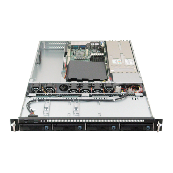
Page 21: As3000 Slot Locations
Installing the Failover Hardware Components AS3000 Slot Locations Each AS3000 server requires a ATTO Celerity FC-81EN Fibre Channel host adapter to connect to the Infortrend RAID array. The card should be installed in the top expansion slot, as shown in the following illustration. - Page 22 Installing the Failover Hardware Components Failover Cluster Connections: Avid ISIS, Redundant-Switch Configuration Interplay Engine Cluster Node 1 AS3000 Back Panel Ethernet to Avid network Fibre Channel switch 1 to Infortrend Ethernet to node 2 (Private network) Infortrend RAID Array Back Panel...
-
Page 23: Failover Cluster Connections, Dual-Connected Configuration
Installing the Failover Hardware Components Failover Cluster Connections, Dual-Connected Configuration Make the following cable connections to add a failover cluster to an Avid ISIS environment as a dual-connected configuration: • First cluster node (AS3000): Top-right network interface connector (2) to the ISIS left subnet (VLAN 10 public... - Page 24 Installing the Failover Hardware Components Failover Cluster Connections, Avid ISIS, Dual-Connected Configuration Interplay Engine Cluster Node 1 AS3000 Back Panel Ethernet to ISIS left subnet Ethernet to ISIS right subnet Fibre Channel to Infortrend Ethernet to node 2 (Private network)
-
Page 25: Clustering Technology And Terminology
Clustering Technology and Terminology Clustering Technology and Terminology Clustering is not always straightforward, so it is important that you get familiar with the technology and terminology of failover clusters before you start. A good source of information is the Windows Server 2008 R2 Failover Clustering resource site: www.microsoft.com/windowsserver2008/en/us/failover-clustering-technical.aspx The following link describes the role of the quorum in a cluster: http://technet.microsoft.com/en-us/library/cc770620(WS.10).aspx... -
Page 26: Creating A Microsoft Failover Cluster
Do not install any other software on the cluster machines except the Interplay engine. For example, Media Indexer software needs to be installed on a different server. For complete installation instructions, see the Avid Interplay Software Installation and Configuration Guide. -
Page 27: Before You Begin The Server Failover Installation
Server Execution User. • Be prepared to install and set up an Avid shared-storage client on both servers after the failover cluster configuration and Interplay Engine installation is complete. See the Avid... -
Page 28: Requirements For Domain User Accounts
The Server Execution User is not used to start the cluster service for a Windows Server 2008 installation. Windows Server 2008 uses the system account to start the cluster service. The Server Execution User is used to start the Avid Workgroup Engine Monitor and the Avid Workgroup TCP COM Bridge. - Page 29 Before You Begin the Server Failover Installation Requirements for Microsoft cluster creation: To create a user with the necessary rights for Microsoft cluster creation, you need to work with the site’s IT department to access Active Directory (AD). Depending on the account policies of the site, you can grant the necessary rights for this user in one of the following ways: Make the user a member of the Domain Administrators group.
-
Page 30: List Of Ip Addresses And Network Names
The number of IP addresses you need depends on your configuration: • An Avid ISIS environment with a redundant-switch configuration requires 4 public IP addresses and 2 private IP addresses • An Avid ISIS environment with a dual-connected configuration requires 8 public IP... - Page 31 Before You Begin the Server Failover Installation The following table provides a list of example names that you can use when configuring the cluster for an ISIS redundant-switch configuration. You can fill in the blanks with your choices to use as a reference during the configuration process. IP Addresses and Node Names: ISIS Redundant-Switch Configuration Node or Service Item Required...
- Page 32 Before You Begin the Server Failover Installation The following table provides a list of example names that you can use when configuring the cluster for an ISIS dual-connected configuration. Fill in the blanks to use as a reference. IP Addresses and Node Names: ISIS Dual-Connected Configuration Node or Service Item Required Example Name...
-
Page 33: Active Directory And Dns Requirements
Before You Begin the Server Failover Installation IP Addresses and Node Names: ISIS Dual-Connected Configuration (Continued) Node or Service Item Required Example Name Where Used Interplay Engine • 1 Network Name SEENGINE “Specifying the service (virtual host name) Interplay Engine Details” on page 76 ______________________ “Specifying the Interplay... -
Page 34: Preparing The Server For The Cluster Service
Preparing the Server for the Cluster Service Windows Server 2003: DNS Entries DNS Dynamic DNS Static Computer Account Component in Active Directory Entry Entry Cluster node 1 node_1_name Cluster node 2 node_2_name MSDTC Microsoft cluster service Interplay Engine service (virtual) No a. -
Page 35: Changing Default Settings For The Atto Card On Each Node
Preparing the Server for the Cluster Service Changing Default Settings for the ATTO Card on Each Node You need to use the ATTO Configuration Tool to change some default settings on each node in the cluster. To change the default settings for the ATTO card: 1. -
Page 36: Changing Windows Server Settings On Each Node
7. On the other node, repeat steps 1 through 6. Changing Windows Server Settings on Each Node The latest image for the AS3000 Windows Server 2008 R2 Standard x64 (Rev. 4, October 17, 2012) includes system settings that previously required manual changes. For information about these settings, see “Windows Server Settings Included in Latest Image”... - Page 37 Preparing the Server for the Cluster Service The Network Connections window opens. The top left network connector on the AS3000 (number 1) is not used and can be disabled. To disable it, select the corresponding Local Area Connection entry and select File > Disable.
- Page 38 Avid suggests that you use the naming conventions provided in the previous table. 5. Depending on your Avid network and the device you selected, type a new name for the network connection and press Enter.
-
Page 39: Configuring The Private Network Adapter On Each Node
Preparing the Server for the Cluster Service The following Network Connections window shows the new names used in a dual-connected Avid ISIS environment. 7. Close the Network Connections window. 8. Repeat this procedure on node 2, using the same names that you used for node 1. - Page 40 Preparing the Server for the Cluster Service Select this check box. All others are unchecked. 5. Select Internet Protocol Version 4 (TCP/IPv4) and click Properties. The Internet Protocol Version 4 (TCP/IPv4) Properties dialog box opens.
- Page 41 Preparing the Server for the Cluster Service Type the private IP address for the node you are configuring. 6. On the General tab of the Internet Protocol (TCP/IP) Properties dialog box: a. Select “Use the following IP address.” b. IP address: type the IP address for the Private network connection for the node you are configuring.
- Page 42 Preparing the Server for the Cluster Service 8. On the DNS tab, make sure no values are defined and that the “Register this connection’s addresses in DNS” and “Use this connection’s DNS suffix in DNS registration” are not selected. 9. On the WINS tab, do the following: Make sure no values are defined in the WINS addresses area.
-
Page 43: Configuring The Binding Order Networks On Each Node
Preparing the Server for the Cluster Service Configuring the Binding Order Networks on Each Node Repeat this procedure on each node and make sure the configuration matches on both nodes. To configure the binding order networks: 1. On node 1, click Start > Control Panel > Network and Sharing Center. The Network and Sharing Center window opens. -
Page 44: Configuring The Public Network Adapter On Each Node
Make sure you configure the IP address network interfaces for the public network adapters as you normally would. For examples of public network settings, see “List of IP Addresses and Network Names” on page Avid recommends that you disable IPv6 for the public network adapters, as shown in the following illustration:... -
Page 45: Configuring The Cluster Shared-Storage Raid Disks On Each Node
Preparing the Server for the Cluster Service Configuring the Cluster Shared-Storage RAID Disks on Each Node Both nodes must have the same configuration for the cluster shared-storage RAID disk. When you configure the disks on the second node, make sure the disks match the disk configuration you set up on the first node. - Page 46 Preparing the Server for the Cluster Service 3. If the disks are offline, right-click Disk 1 (in the left column) and select Online. Repeat this action for Disk 3. Do not bring Disk 2 online. 4. If the disks are not already initialized, right-click Disk 1 (in the left column) and select Initialize Disk.
- Page 47 Preparing the Server for the Cluster Service Select Disk 1 and Disk 3 and make sure that MBR is selected. Click OK. 5. Use the New Simple Volume wizard to configure the disks as partitions. Right-click each disk, select New Simple Volume, and follow the instructions in the wizard. Use the following names and drive letters: Infortrend Infortrend...
- Page 48 Preparing the Server for the Cluster Service Do not assign a name or drive letter to Disk 2. If you need to change the drive letter after running the wizard, right-click the drive letter in the right column and select Change Drive Letter or Path. If you receive a warning tells you that some programs that rely on drive letters might not run correctly and asks if you want to continue.
-
Page 49: Configuring The Cluster Service
Configuring the Cluster Service 9. Boot the first node. 10. Open the Disk Management tool to make sure that the disks are still online and have the correct drive letters assigned. At this point, both nodes should be running. Configuring the Cluster Service Take the following steps to configure the cluster service: 1. - Page 50 Configuring the Cluster Service To install the Failover Clustering featurer: 1. On the first node, right-click My Computer and select Manage. The Server Manager window opens. 2. In the Server Manager list, click Features. 3. On the right-side of the Features window, click Add Features. A list of features is displayed.
- Page 51 Configuring the Cluster Service 6. Click Close. To check if the feature was installed, open the Server Manager and open Features. The Failover Cluster Manager should be displayed. 7. Repeat this procedure on the second node. Displaying the List of Server Features If a list of server features does not display and “Error”...
-
Page 52: Creating The Cluster Service
Configuring the Cluster Service 5. Click OK. Creating the Cluster Service To create the cluster service: 1. Make sure all storage devices are turned on. 2. Log in to the operating system using the cluster installation account (see “Requirements for Domain User Accounts”... - Page 53 Configuring the Cluster Service 5. Click Create a Cluster. The Create Cluster Wizard opens with the Before You Begin window. 6. Review the information and click Next (you will validate the cluster in a later step). 7. In the Select Servers window, type the simple computer name of node 1 and click Add. Then type the computer name of node 2 and click Add.
- Page 54 Configuring the Cluster Service If you cannot add the remote node to the cluster, and receive an error message “Failed to connect to the service manager on <computer-name>,” check the following: - Make sure that the time settings for both nodes are in sync. - Make sure that the login account is a domain account with the required privileges.
- Page 55 Configuring the Cluster Service If you are configuring a dual-connected cluster, you need to add a second IP address after renaming and deleting cluster disks. This procedure is described in “Adding a Second IP Address to the Cluster” on page 11.
- Page 56 The following illustration shows components of a dual-connected cluster. Cluster Network 1 and Cluster Network 2 are external networks connected to VLAN 10 and VLAN 20 on Avid ISIS, and Cluster Network 3 is a private, internal network for the heartbeat.
- Page 57 Configuring the Cluster Service It is possible that Cluster Network 2 (usually Right or VLAN 20) is not configured to be external by the Create Cluster Wizard. In this case, right-click Cluster Network 2, select Properties, and check “Allow clients to connect through this network.”...
-
Page 58: Renaming The Cluster Networks In The Failover Cluster Manager
Configuring the Cluster Service The following illustration shows components of a cluster in a redundant-switch ISIS environment. Cluster Network 1 is an external network connecting to one of the redundant switches, and Cluster Network 2 is a private, internal network for the heartbeat. Renaming the Cluster Networks in the Failover Cluster Manager You can more easily manage the cluster by renaming the networks that are listed under the Failover Cluster Manager. - Page 59 Configuring the Cluster Service 5. Click in the Name text box, and type a meaningful name, for example, a name that matches the name you used in the TCP/IP properties. For a redundant-switch configuration, use Public. For a dual-connected configuration, use Left, as shown in the following example. For this network, keep the option “Allow clients to connect through this network.”...
-
Page 60: Renaming Cluster Disk 1 And Deleting The Remaining Cluster Disks
Configuring the Cluster Service For this private network, leave the option “Allow clients to connect through this network” unchecked. Renaming Cluster Disk 1 and Deleting the Remaining Cluster Disks You can more easily manage the cluster by renaming Cluster Disk 1, which is listed under the Failover Cluster Manager. - Page 61 Configuring the Cluster Service 4. In the Storage window, right-click Cluster Disk 1 and select Properties. The Properties dialog box opens. 5. In the Resource Name dialog box, type a name for the cluster disk. In this case, Cluster Disk 1 is the Quorum disk, so type Quorum as the name.
-
Page 62: Adding A Second Ip Address To The Cluster
Configuring the Cluster Service To remove all disks other than Cluster Disk 1 (Quorum) 1. In the Storage window, right-click Cluster Disk 2 and select Delete. 2. In the Storage window, right-click Cluster Disk 3 if available (or Databases, if you renamed it) and select Delete. - Page 63 Configuring the Cluster Service 3. Click Networks. Make sure that Cluster Use is enabled for both ISIS networks, as shown in the following illustration. If a network is not enabled, right-click the network, select Properties, and select “Allow clients to connect through this network.”...
- Page 64 Configuring the Cluster Service 4. In the Failover Cluster Manager, select the cluster application by clicking on the Cluster name in the left column of the Failover Cluster Manager. 5. In the Actions panel (right column), select Properties in the Name section. The Properties dialog box opens.
- Page 65 Configuring the Cluster Service In the network column, if <unknown network> or <No Network> is displayed instead of the network identifier, close the Server Manager window, and after waiting a few seconds open it again. 6. In the General tab, do the following: a.
- Page 66 Configuring the Cluster Service 7. Click Apply. A confirmation box asks you to confirm that all cluster nodes need to be restarted. You will restart the nodes later in this procedure, so select Yes.
-
Page 67: Testing The Cluster Installation
Configuring the Cluster Service 8. Click the Dependencies tab and check if the new IP address was added with an OR conjunction. If the second IP address is not there, click “Click here to add a dependency.” Select “OR” from the list in the AND/OR column and select the new IP address from the list in the Resource column. - Page 68 Configuring the Cluster Service In the following figure, warrm-ipe3 (node 1) is the current owner of the Quorum disk and is the active node. 3. Open a Command Prompt and enter the following command: cluster group “Cluster Group” /move:node_hostname This command moves the cluster group, including the Quorum disk, to the node you specify. To test the failover, use the hostname of the non-active node.
- Page 69 Configuring the Cluster Service 4. Open the Server Manager and select Features > Failover Cluster Manager > cluster_name > Storage. Make sure that the Quorum disk is online and that current owner is node 2, as shown in the following illustration. 5.
-
Page 70: Installing The Interplay Engine For A Failover Cluster
Installing the Interplay Engine for a Failover Cluster After you set up and configure the cluster, you need to install the Interplay Engine software on both nodes. The following topics describe installing the Interplay Engine and other final tasks: • Disabling Any Web Servers •... -
Page 71: Installing The Interplay Engine On The First Node
Installing the Interplay Engine on the First Node Installing the Interplay Engine on the First Node The following sections provide procedures for installing the Interplay Engine on the first node. For a list of example entries, see “List of IP Addresses and Network Names” on page •... -
Page 72: Bringing The Shared Database Drive Online
Installing the Interplay Engine on the First Node When installing the Interplay Engine for the first time on a machine with cluster services, you are asked to choose between clustered and regular installation. The installation on the second node (or later updates) reuses the configuration from the first installation without allowing you to change the cluster-specific settings. - Page 73 Installing the Interplay Engine on the First Node If Disk 3 is online, you can skip the following steps. 3. Right-click Disk 3 (in the left column) and select Online. 4. Make sure the drive letter is correct (S:) and the drive is named Databases. If not, you can change it here.
-
Page 74: Starting The Installation And Accepting The License Agreement
The Specify Installation Type dialog box opens. 7. Continue the installation as described in the next topic. If you receive a message that the Avid Workgroup Name resource was not found, you need to check the registry. See “Changing the Resource Name of the Avid Workgroup Server” on... - Page 75 Installing the Interplay Engine on the First Node • “Specifying the Share Name” on page 81 • “Specifying the Configuration Server” on page 82 • “Specifying the Server User” on page 83 • “Specifying the Server Cache” on page 84 •...
- Page 76 Installing the Interplay Engine on the First Node 3. Select Cluster and click Next to continue the installation in cluster mode. The Specify Interplay Engine Details dialog box opens. Specifying the Interplay Engine Details In this dialog box, provide details about the Interplay Engine.
- Page 77 Installing the Interplay Engine on the First Node To specify the Interplay Engine details: 1. Type the following values: Virtual IP address: This is the Interplay Engine service IP Address, not the Cluster service IP address. For a list of examples, see “List of IP Addresses and Network Names”...
- Page 78 DNS so that clients can find the server without having to specify its address. The Server Name is used by clients to identify the server. If you only use Avid Interplay Clients on Windows computers, you can use the Network Name as the server name. If ®...
- Page 79 In this dialog box specify the folder in which you want to install the Interplay Engine program files. To specify the destination location: 1. Avid recommends that you keep the default path C:\Program Files\Avid\Avid Interplay Engine. Under no circumstances attempt to install to a shared disk; independent installations are required on both nodes.
- Page 80 Installing the Interplay Engine on the First Node Specifying the Default Database Folder In this dialog box specify the folder where the database data is stored. To specify the default database folder: 1. Type S:\Workgroup_Databases. Make sure the path specifies the shared drive (S:). This folder must reside on the shared drive that is owned by the resource group of the server.
- Page 81 Windows Explorer. For security reasons, Avid recommends using a “$” at the end of the share name. If you use the default settings, the directory S:\Workgroup_Databases is accessible as \\InterplayEngine\WG_Database$.
- Page 82 Interplay Archive Engine A Central Configuration Server (CCS) is an Avid Interplay Engine with a special module that is used to store server and database-spanning information. For more information, see the Avid Interplay Engine and Avid Interplay Archive Engine Administration Guide.
- Page 83 The installer cannot check the username or password you type in this dialog. Make sure that the password is set correctly, or else you will need to uninstall the server and repeat the entire installation procedure. Avid does not recommend changing the Server Execution User in cluster mode afterwards, so choose carefully.
- Page 84 If necessary, you can change the name of the Server Execution User after the installation. For more information, see “Troubleshooting the Server Execution User Account” and “Re-creating the Server Execution User” in the Avid Interplay Engine and Avid Interplay Archive Engine Administration Guide and the Interplay ReadMe.
- Page 85 Installing the Interplay Engine on the First Node Enabling Email Notifications The first time you install the Avid Interplay Engine, the Enable Email Notification dialog box opens. The email notification feature sends emails to your administrator when special events, such as “Cluster Failure,” “Disk Full,” and “Out Of Memory” occur. Activate email notification if you want to receive emails on special events, server or cluster failures.
- Page 86 SMTP server. The notification feature needs the SMTP server in order to send emails. If you do not know this IP, ask your administrator. 3. If you also want to inform Avid Support automatically using email if problems arise, select “Send critical notifications also to Avid Support.”...
- Page 87 Installing the Interplay Engine on the First Node Installing the Interplay Engine for a Custom Installation on the First Node In this dialog box, begin the installation of the engine software. To install the Interplay Engine software: 1. Click Next. Use the Back button to review or change the data you have entered.
- Page 88 Installing the Interplay Engine on the First Node The Windows Firewall is turned off by the server image (see “Windows Server Settings Included in Latest Image” on page 112). If the Firewall is turned on, you get messages that the Windows Firewall has blocked nxnserver.exe (the Interplay Engine) and the Apache server from public networks.
-
Page 89: Checking The Status Of The Resource Group
The installation procedure requires the machine to restart (up to twice). For this reason it is very important that the other node is shut down, otherwise the current node loses ownership of the Avid Workgroup resource group. This applies to the installation on the first node only. Subsequent installations should be run as described in “Updating a Clustered Installation... - Page 90 Installing the Interplay Engine on the First Node The Server Name and IP Address, File Server, and Avid Workgroup Disk resources should be online and all other resources offline. S$ and WG_Database$ should be listed in the Shared Folders section.
-
Page 91: Creating The Database Share Manually
If you are setting up an Avid ISIS dual-connected configuration, proceed to “Adding a Second IP Address (Dual-Connected Configuration)” on page Avid does not recommend starting the server at this stage, because it is not installed on the other node and a failover would be impossible. Creating the Database Share Manually If the File Server resource or the database share (WG_Database$) is not created (see “Checking... -
Page 92: Adding A Second Ip Address (Dual-Connected Configuration)
Installing the Interplay Engine on the First Node Adding a Second IP Address (Dual-Connected Configuration) If you are setting up an Avid ISIS dual-connected configuration, you need use the Failover Cluster Manager to add a second IP address. To add a second IP address: 1. - Page 93 Installing the Interplay Engine on the First Node Note that the Resource Name is listed as “Avid Workgroup Name.” Make sure to check the Resource Name after adding the second IP address and bringing the resources on line in step 9.
- Page 94 Installing the Interplay Engine on the First Node The second ISIS sub-network and a static IP Address are already displayed. 5. Type the second Interplay Engine service Avid ISIS IP address. See “List of IP Addresses and Network Names” on page 30.
- Page 95 Installing the Interplay Engine on the First Node 6. Check that you entered the IP address correctly, then click Apply. 7. Click the Dependencies tab and check that the second IP address was added, with an OR in the AND/OR column. 8.
- Page 96 Installing the Interplay Engine on the First Node 9. Bring the Name, both IP addresses, and the File Server resource online by doing one of the following: Right-click the resource and select “Bring this resource online.” Select the resources and select “Bring this resource online” in the Actions panel. The following illustration shows the resources online.
- Page 97 Installing the Interplay Engine on the First Node 10. Right-click the Name resource and select Properties.
-
Page 98: Changing The Resource Name Of The Avid Workgroup Server
Changing the Resource Name of the Avid Workgroup Server If you find that the resource name of the Avid Workgroup Server application is not “Avid Workgroup Name” (as displayed in the properties for the Server Name), you need to change the name in the Windows registry. - Page 99 2. Browse through the GUID named subkeys looking for the one subkey where the value “Type” is set to “Network Name” and the value “Name” is set to <incorrect_name>. 3. Change the value “Name” to “Avid Workgroup Name.” 4. Do the following to shut down the cluster: Make sure you have edited the registry entry before you shut down the cluster.
-
Page 100: Installing The Interplay Engine On The Second Node
Installing the Interplay Engine on the Second Node 5. Do the following to bring the cluster on line: a. In the Server Manager tree (left panel) select the cluster. b. In the context menu or the Actions panel on the right side, select “Start Cluster Service.” Installing the Interplay Engine on the Second Node To install the Interplay Engine on the second node: 1. -
Page 101: Bringing The Interplay Engine Online
5. The installation procedure requires the machine to restart (up to twice). Allow the restart as requested. If you receive a message that the Avid Workgroup Name resource was not found, you need to check the registry. See “Changing the Resource Name of the Avid Workgroup Server” on... -
Page 102: After Installing The Interplay Engine
After Installing the Interplay Engine After you install the Interplay Engine, install the following applications on both nodes: • Interplay Access: From the Interplay Server Installer Main Menu, select Servers > Avid Interplay Engine > Avid Interplay Access. • Avid ISIS client: See the Avid ISIS System Setup Guide. -
Page 103: Creating An Interplay Database
7. Keep the root folder for the New Data Location (Assets). If you are creating a split database, this entry should show the Avid shared-storage workspace that you set in the Server Settings view. For more information, see the Avid Interplay Engine and Avid Interplay Archive Engine Administration Guide. -
Page 104: Installing A Permanent License
There is no time limit for this license. A permanent license is provided by Avid in the form of a file (*.nxn), usually on a USB flash drive. A license for an Interplay Engine failover cluster includes two hardware IDs. You install this license through the Interplay Administrator. -
Page 105: Updating A Clustered Installation (Rolling Upgrade)
For information about updating specific versions of the Interplay Engine and a cluster, see the Avid Interplay ReadMe. The ReadMe describes an alternative method of updating a cluster, in which you lock and deactivate the database before you begin the update. - Page 106 Updating a Clustered Installation (Rolling Upgrade) To update a cluster: 1. On either node, determine which node is active: a. Right-click My Computer and select Manage. The Server Manager window opens. b. In the Server Manager list, open Features and click Failover Cluster Manager. c.
-
Page 107: Uninstalling The Interplay Engine On A Clustered System
Engine offline and will update the cluster resources. 7. The installer displays a dialog box that asks you to move the Avid Workgroup Server to the second node. Move the application, then click OK in the installation dialog box to continue. - Page 108 3. Make sure that both nodes are running before you start the uninstaller. 4. On the inactive node (the node that does not own the Avid Workgroup Server resource group), start the uninstaller by selecting Programs > Avid > Avid Interplay Engine >...
- Page 109 Uninstalling the Interplay Engine on a Clustered System 11. Click Yes. 12. When you are asked if you want to restart the system, click Yes. 13. At the end of the uninstallation process, if you are asked to restart the system, click Yes. 14.
-
Page 110: Automatic Server Failover Tips And Rules
Automatic Server Failover Tips and Rules This chapter provides some important tips and rules to use when configuring the automatic server failover. Don't Access the Interplay Engine Through Individual Nodes Don't access the Interplay Engine directly through the individual machines (nodes) of the cluster. Use the virtual network name or IP address that has been assigned to the Interplay Engine resource group (see “List of IP Addresses and Network Names”... - Page 111 Consider Disabling Failover When Experimenting If you are performing changes that could make the Avid Interplay Engine fail, consider disabling failover. The default behavior is to restart the server twice (threshold = 3) and then initiate the failover, with the entire procedure repeating several times before final failure.
-
Page 112: Appendix A Windows Server Settings Included In Latest Image
Windows Server Settings Included in Latest Image The latest image for the AS3000 Windows Server 2008 R2 Standard x64 (Rev. 4, October 17, 2012) includes system settings that required manual changes in previous versions of the image. This appendix lists those settings for reference. - Page 113 To create a new GUIDs: 1. Disconnect the ISIS client from the System Director and disconnect the network cables from all network ports at the back of the AS3000. 2. Use the registry editor to delete registry keys, as follows: a.
- Page 114 Creating New GUIDs for the AS3000 Network Adapters 6. In the pop-up dialog box, make sure that “Delete the driver software for this device” is not selected, then click OK. After the last adapter is removed, the Network Adapters category disappears.
-
Page 115: Removing The Web Server Iis Role
Removing the Web Server IIS Role Removing the Web Server IIS Role This procedure is not needed with the latest (Rev. 4) server image. To remove the Web Server IIS role: 1. Click Start > All Programs> Administrative Tools > Server Manager. 2. - Page 116 Removing the Failover Clustering Feature 4. Clear the check box for Failover Clustering. A message asks if you have removed this server from a cluster. Select “Yes.” 5. In the Select Features screen, click Next. The Confirm Removal Selections screen opens.
- Page 117 Removing the Failover Clustering Feature 6. Click Remove. 7. Follow the system prompts to restart the server. The following illustration shows the Removal Results screen that is displayed after you restart.
-
Page 118: Disabling Ipv6
Disabling IPv6 Disabling IPv6 Disabling IPv6 completely is no longer recommended. IPv6 is enabled in the latest (Rev. 4) image. Binding network interface cards (NICs) to IPv6 is not recommended. -
Page 119: Switching The Server Role To Application Server
Switching the Server Role to Application Server Switching the Server Role to Application Server This procedure is not needed with the latest (Rev. 4) server image. To switch the Server Role to Application Server: 1. Click Control Panel > System and Security > System. The System control panel opens. - Page 120 Switching the Server Role to Application Server 3. Click the Advanced tab and click Settings in the Performance area. The Performance Options dialog box opens. 4. Click the Advanced tab.
-
Page 121: Disabling The Windows Firewall
Disabling the Windows Firewall 5. In the Processor scheduling area, under “Adjust for best performance of,” select Programs, as shown in the following illustration. 6. Click Apply, then click OK to close the window. 7. Click OK to close the System properties window, then close the System window. Disabling the Windows Firewall This procedure is not needed with the latest (Rev. - Page 122 Disabling the Windows Firewall 2. In the Actions section on the right, select Properties, as shown in the following illustration. 3. Set the Firewall state to Off in at least the Domain and the Private Profile tabs. If your site allows it, also set the state to Off in the Public Profile tab. The following illustration shows the Firewall state tuned off for the Domain Profile.
- Page 123 Disabling the Windows Firewall 4. Click OK. The Overview section in the center column shows that the firewall is off, as shown in the following illustration.
-
Page 124: Index
Cluster installation running on a failover cluster updating Apache web server Cluster installation and administration account on failover cluster described AS3000 server Cluster networks slot locations (failover cluster) renaming in Failover Cluster Manager ATTO card Cluster service setting link speed... - Page 125 Index Avid ISIS dual-connected configuration preparation for installing on first node Avid ISIS redundant-switch configuration Server Execution User, specifying for failover before installation cluster configurations share name for failover cluster hardware and software requirements specify engine name installation overview specifying server cache...
- Page 126 Public Network configuring for failover cluster for failover cluster specifying for Interplay Engine Public network adapter Slot locations configuring AS3000 server (failover cluster) Software requirements for failover cluster system Subnet Mask Quorum disk configuring Quorum resource defined Training services...
- Page 127 Index...
- Page 128 Avid Technical Support (USA) Product Information 75 Network Drive Visit the Online Support Center at For company and product information, Burlington, MA 01803-2756 USA www.avid.com/support visit us on the web at www.avid.com...
Need help?
Do you have a question about the AS3000 and is the answer not in the manual?
Questions and answers