Table of Contents
Advertisement
Quick Links
Advertisement
Table of Contents

Subscribe to Our Youtube Channel
Related Manuals for Rockwell Automation Allen-Bradley FLEX Ex 1797-IRT8


Summary of Contents for Rockwell Automation Allen-Bradley FLEX Ex 1797-IRT8
- Page 1 FLEX Ex Thermocouple/ RTD/mV Input Module Cat. No. 1797-IRT8 User Manual...
- Page 2 • avoid a hazard • recognize the consequences Identifies information that is critical for successful IMPORTANT application and understanding of the product. Allen-Bradley, FLEX Ex, FLEX I/O, and ControlNet Ex are trademarks of Rockwell Automation ControlNet is a trademark of ControlNet International...
- Page 3 Preface Using This Manual ™ Why Read this Manual This manual shows you how to use your FLEX Ex thermocouple/ ™ RTD/mV module with the ControlNet Ex products and ControlNet network. The manual helps you install, program, and troubleshoot your module. Who Should Read this You must be able to program and operate a ControlNet Ex product ™...
- Page 4 Using This Manual For Additional For additional information on FLEX Ex systems and modules, refer to the following documents, Information Publications Catalog Description Installation User Number Instructions Manual 1797 Series FLEX Ex Product Data 1797-2.1 (Product data) 1797 Series FLEX Ex System Overview 1797-2.2 (System overview)
-
Page 5: Table Of Contents
Table of Contents Important User Information ......2 Preface Using This Manual Why Read this Manual......3 Who Should Read this Manual . - Page 6 Table of Contents Chapter 3 How to Install Your FLEX Ex What this Chapter Contains ......3-1 Before You Install Your Analog Module.
- Page 7 Table of Contents Chapter 5 Calibrating Your Module What This Chapter Contains ..... . . 5-1 When and How to Calibrate Your FLEX Ex Thermocouple/RTD/mV Input Module.
- Page 8 Table of Contents Appendix B Programming the FLEX Ex I/O What this Chapter Contains ......B-1 Enter Block Transfer Modules Instructions.
-
Page 9: For Additional Information
Chapter About the FLEX Ex Thermocouple/RTD/mV Input Module What this Chapter Read this chapter to familiarize yourself with the 1797-IRT8 input module. Contains For information on: See page: What the FLEX Ex Thermocouple/ RTD/mV Modules Do How FLEX Ex Thermocouple/RTD/mV Modules Communicate with Programmable Controllers Features of Your Module... -
Page 10: Events Following Power-Up
About the FLEX Ex Thermocouple/RTD/mV Input Module How FLEX Ex FLEX Ex thermocouple/RTD/mV modules provide best utility when used with ControlNet Ex products on the ControlNet network. Data Thermocouple/RTD/mV connections are established between the I/O module and an Modules Allen-Bradley programmable controller to transfer information between the two at a scheduled rate. -
Page 11: Indicators
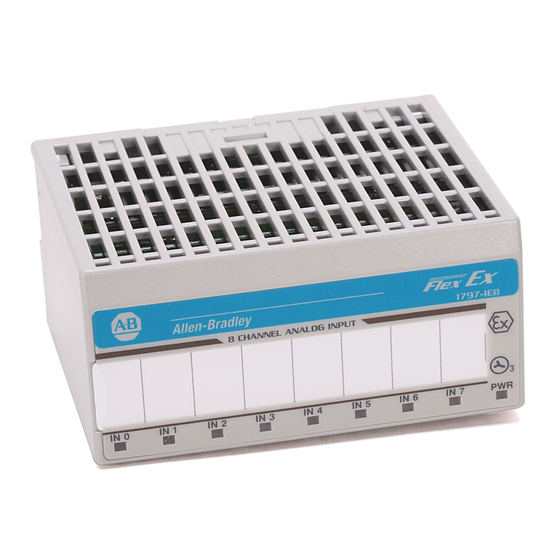
About the FLEX Ex Thermocouple/RTD/mV Input Module Indicators Indicators are provided to identify input or output fault conditions, and to show when power is applied to the module. 1797-IRT8 Module Type Removable Label 1797-IRT8 Keyswitch Position Indicator (#2) Power On Indicator Input Designators 40070 Using Alarms on the... -
Page 12: Data Format Alarm Example
About the FLEX Ex Thermocouple/RTD/mV Input Module Data Format Alarm Example In this example, the normal active data range is 4-20mA. The alarms are generated in three overlapping bands. PHYSICAL INPUT SIGNAL RANGE underrange normal signal range overrange CJC fault CJC fault open wire fault Minumum... -
Page 13: Data Formats And Fault Modes
About the FLEX Ex Thermocouple/RTD/mV Input Module Data Formats and Fault Modes The tables below shows the bit settings for the data formats and fault modes for your FLEX Ex thermocouple/RTD/mV module. Data Formats Bit 11 10 09 08 Data type for channels 0 thru 7 C (see note) F (see note) K (see note) - Page 14 About the FLEX Ex Thermocouple/RTD/mV Input Module Publication 1797-6.5.2 - February 2001...
-
Page 15: What This Chapter Contains
Chapter Understanding Configurable FLEX Ex Thermocouple/RTD/mV Input Module Features What this Chapter Read this chapter to familiarize yourself with configurable features on the 1797-IRT8 module. Contains For information on: See page: Setting a FLEX Ex Thermocouple/RTD Module’s Operating Status Input Type Select Sensor Type Select Data Format Preset Temperature Select... -
Page 16: Setting A Flex Ex Thermocouple/Rtd Module's Operating Status
Understanding Configurable FLEX Ex Thermocouple/RTD/mV Input Module Features Setting a FLEX Ex Input Type Select Thermocouple/RTD Select the thermocouple or RTD mode for input channel groups 0-3 Module’s Operating and 4-7. If 2 is selected, the module defaults to thermocouple. If 3 is Status selected, the module defaults to RTD. -
Page 17: Input Filter Cutoff
Understanding Configurable FLEX Ex Thermocouple/RTD/mV Input Module Features Bits 00-03 Sensor Type (Thermocouple or RTD) RTD Type Sensor type for channels 0 through 3 Resistance (default) 100 ohm Pt α = 0.00385 Euro (–200 to +870°C) 200 ohm Pt α = 0.00385 Euro (–200 to +400°C) 100 ohm Pt α... -
Page 18: Data Format
Understanding Configurable FLEX Ex Thermocouple/RTD/mV Input Module Features Input Filter Cutoff bits Definition Hardware filtering only (default filtering) 600Hz (1.7ms) 40Hz (25ms) 10Hz (100ms) (250ms) (500ms) (1s) 0.5Hz (2s) 0.2Hz (5s) Choose the best input filter cutoff in your programming software. Data Format You must choose a module data format in your user program. -
Page 19: Sensor Mode Select
Understanding Configurable FLEX Ex Thermocouple/RTD/mV Input Module Features Sensor Mode Select Selects the sensor mode for input channels 0-3 and 4-7. If using cold junction compensation, both CJCs must be installed. The difference between the CJCs will be linearly apportioned to each thermocouple channel based on its position across the base. -
Page 20: Rtd Loop Resistance Offset Select
Understanding Configurable FLEX Ex Thermocouple/RTD/mV Input Module Features Bits 03-05 Reference Junction – used when input type is set to thermocouple and sensor mode is set to fixed compensation. Sets a fixed reference junction to compensate all thermocouple channels. Reference Junction 0°C 20°C 25°C... -
Page 21: Fault Mode Select
Understanding Configurable FLEX Ex Thermocouple/RTD/mV Input Module Features Fault Mode Select Select whether the channel fault detection is enabled or disabled for channels 0-3 and 4-7. Range: 0 = disable, 1 = fault detection enabled (wire off, mV overvoltage, RTD open). Default = 0. Bits 06-07 Fault Mode bits –... -
Page 22: Underrange Alarm
Understanding Configurable FLEX Ex Thermocouple/RTD/mV Input Module Features IRT8 Specific alarming performance PHYSICAL INPUT SIGNAL RANGE underrange normal signal range overrange CJC fault CJC fault open wire fault Sensor Type IEC PT100 -200C +870C ~ 520ohm equivalent -200C +400C ~ 520ohm equivalent IEC PT200 ~ 520ohm equivalent -200C... -
Page 23: Fault Alarm
Understanding Configurable FLEX Ex Thermocouple/RTD/mV Input Module Features Fault Alarm The module has individual channel fault alarms for a broken or detached wire. In any mode, if a broken/detached lead is detected, the data value is forced to maximum. Once the alarm is issued, it remains active as long as the input signal is faulted. - Page 24 2-10 Understanding Configurable FLEX Ex Thermocouple/RTD/mV Input Module Features Publication 1797-6.5.2 - February 2001...
-
Page 25: What This Chapter Contains
Chapter How to Install Your FLEX Ex Thermocouple/ RTD/mV Module What this Chapter Contains Read this chapter to install the 1797-IRT8 thermocouple/RTD/mV module. For information on: See page: Before You Install Your Analog Module Compliance to European Union Directives Installation in Zone 1 Removal and Insertion Under Power Installing the Module Connecting Wiring to the FLEX Ex... -
Page 26: Compliance To European Union Directives
How to Install Your FLEX Ex Thermocouple/RTD/mV Module Compliance to European If this product has the CE mark, it is approved for installation within the European and EEA regions. It has been designed and tested to Union Directives meet the following directives. EMC Directive This product is tested to meet the Council Directive 89/336/EC Electromagnetic Compatibility (EMC) by applying the following... -
Page 27: Electrostatic Charge
How to Install Your FLEX Ex Thermocouple/RTD/mV Module Electrostatic Charge Protect the system against electrostatic charge. Post a sign near this module: Attention! Avoid electrostatic charge. For your convenience, a sign which can be cut out and posted is included in this user manual before the back cover. - Page 28 How to Install Your FLEX Ex Thermocouple/RTD/mV Module 1. Remove the cover plug in the male connector of the unit to which you are connecting this terminal base unit. 2. Check to make sure that the 16 pins in the male connector on the adjacent device are straight and in line so that the mating female connector on this terminal base unit will mate correctly.
- Page 29 How to Install Your FLEX Ex Thermocouple/RTD/mV Module 5. Rotate the terminal base onto the DIN rail with the top of the rail hooked under the lip on the rear of the terminal base. Use caution to make sure that the female flexbus connector does not strike any of the pins in the mating male connector.
-
Page 30: Panel/Wall Mounting
How to Install Your FLEX Ex Thermocouple/RTD/mV Module Panel/Wall Mounting Installation on a wall or panel consists of: • laying out the drilling points on the wall or panel • drilling the pilot holes for the mounting screws • mounting the adapter mounting plate •... - Page 31 How to Install Your FLEX Ex Thermocouple/RTD/mV Module 1. Lay out the required points on the wall/panel as shown in the drilling dimension drawing. Drilling Dimensions for Panel/Wall Mounting of FLEX Ex I/O (35.5) (35.5) (58.5) (35.5) (58.5) (40.5) (15.6) .83 (21) (50) Inches...
-
Page 32: Mounting The 1797-Irt8 Module On The Terminal
How to Install Your FLEX Ex Thermocouple/RTD/mV Module Mounting the 1797-IRT8 Module on the Terminal Base Unit The 1797-IRT8 module mounts on a 1797-TB3 or TB3S intrinsically safe terminal base unit. 1. Rotate keyswitch (1) on terminal base unit (2) clockwise to position 2 as required for this type of module. -
Page 33: Wiring The Terminal Base Units
How to Install Your FLEX Ex Thermocouple/RTD/mV Module 6. Make certain that you only connect terminal base units to other intrinsically safe system modules or adapters to maintain the integrity of the intrinsically-safe backplane. 7. Remove cap plug (8) and attach another intrinsically safe terminal base unit to the right of this terminal base unit if required. -
Page 34: Connecting Wiring To The Flex Ex Thermocouple/Rtd/Mv Module
3-10 How to Install Your FLEX Ex Thermocouple/RTD/mV Module Connecting Wiring to the Inputs/Outputs Each input can be operated from a thermocouple (TC), resistance FLEX Ex Thermocouple/ temperature detector (RTD), or millivolt. Do not apply any RTD/mV Module non-intrinsically safe signals to this module. When using an intrinsically safe electrical apparatus according to EN50020, the European directives and regulations must be followed. -
Page 35: Wiring Connections For The 1797-Irt8 Module
How to Install Your FLEX Ex Thermocouple/RTD/mV Module 3-11 Wiring connections for the 1797-IRT8 Module 1. For RTD inputs: a. connect the individual source current input wiring to (+) terminals for each individual channel (0, 4, 8 and 12) on the 0-15 row (A) and terminals 17, 21, 25, and 29 on the 16-33 row (B) as indicated in the table below. - Page 36 3-12 How to Install Your FLEX Ex Thermocouple/RTD/mV Module Connect the following: Type of Input Shield RTD - 2-wire RTD - 3-wire 2-wire RTD RTD - 4-wire Thermocouple Millivolt 1Terminals 16, 33, 40 thru 45 are chassis ground. 3-wire RTD RTD or RTD Source High Signal...
-
Page 37: Grounding The Module
How to Install Your FLEX Ex Thermocouple/RTD/mV Module 3-13 Grounding the Module All I/O wiring must use shielded wire. Shields must be terminated external to the module, such as bus bars and shield-terminating feed throughs. 30820-M Chapter Summary In this chapter, we told you how to install your thermocouple/RTD/ mV module in an existing programmable controller system and how to wire to the terminal base units. - Page 38 3-14 How to Install Your FLEX Ex Thermocouple/RTD/mV Module Publication 1797-6.5.2 - February 2001...
-
Page 39: What This Chapter Contains
Chapter Input, Status, Output and Configuration Files for the Thermocouple/RTD/mV Module on the ControlNet Network What this Chapter Contains Read this chapter to familiarize yourself with input, output and configuration files for the thermocouple/RTD/mV module on ControlNet. For information on: See page: Using Programming Software in Your FLEX Ex Application... -
Page 40: Using Programming Software In Your Flex Ex Application
Input, Status, Output and Configuration Files for the Thermocouple/RTD/mV Module on the ControlNet Network Using Programming When using FLEX Ex thermocouple/RTD/mV modules, you must perform I/O mapping and configure the ControlNet network before Software in Your FLEX Ex generating configuration data for your I/O modules. Application For example, you may use RSNetWorx™... -
Page 41: Scheduled Data-Transfer
Input, Status, Output and Configuration Files for the Thermocouple/RTD/mV Module on the ControlNet Network Scheduled Data-Transfer Scheduled data transfer: • is continuous. • is asynchronous to the controller program scan. • occurs at the actual rate displayed in the Actual Packet Interval field on the programming software ControlNet I/O mapping (monitor) screen Unscheduled Data-Transfer... -
Page 42: I/O Structure
Input, Status, Output and Configuration Files for the Thermocouple/RTD/mV Module on the ControlNet Network For example, a 16 point discrete input module will have up to 2 read words and 1 write word. ControlNet Image Input Size Module Image 1 Word Input Status Size Faults... -
Page 43: Adapter Status Word
Input, Status, Output and Configuration Files for the Thermocouple/RTD/mV Module on the ControlNet Network Adapter Status Word The status word consists of: • I/O module fault bits – 1 status bit for each slot Additionally, in the case of a PLC-5 controller, it adds: •... -
Page 44: Fault State Data
Input, Status, Output and Configuration Files for the Thermocouple/RTD/mV Module on the ControlNet Network Possible causes for an I/O Module Fault are: • transmission errors on the FLEX Ex backplane • a failed module • a module removed from its terminal base •... -
Page 45: Idle State Behavior
Input, Status, Output and Configuration Files for the Thermocouple/RTD/mV Module on the ControlNet Network Idle State Behavior The ControlNet Ex adapter can detect the state of the controlling processor or scanner. Only 2 states can be detected: – run mode, –... -
Page 46: Thermocouple/Rtd/Mv Input Module (1797-Irt8) Image Table Mapping
Input, Status, Output and Configuration Files for the Thermocouple/RTD/mV Module on the ControlNet Network Thermocouple/RTD/mV Input Module (1797-IRT8) Image Table Mapping Module Image Input Data Channel 0 Input Data Channel 1 I/O Image Input Data Channel 2 Input Size Input Data Channel 3 1 to 11 Words Input Data Channel 4 Input Data Channel 5... - Page 47 Input, Status, Output and Configuration Files for the Thermocouple/RTD/mV Module on the ControlNet Network Dec. Bits Input Word Description (Octal Bits) Input Word 8 00-07 Underrange bits – these bits are set if the input signal is below the input channel’s minimum range. Bit 00 corresponds to channel 0, bit 01 corresponds to channel 1, etc.
- Page 48 4-10 Input, Status, Output and Configuration Files for the Thermocouple/RTD/mV Module on the ControlNet Network Configuration Dec. Bits Description Word (Octal Bits) Configuration Bits 00-02 Input Filter Cutoff bits Word 0 Definition Hardware filtering only (default filtering) 40Hz (25ms) 10Hz (100ms) (250ms) (500ms)
- Page 49 Input, Status, Output and Configuration Files for the Thermocouple/RTD/mV Module on the ControlNet Network 4-11 Configuration Dec. Bits Description Word (Octal Bits) Configuration Bits 00-03 Sensor Type (Thermocouple or RTD) Word 1 RTD Type Sensor type for channels 0 through 3 Resistance (default) 100 ohm Pt α...
- Page 50 4-12 Input, Status, Output and Configuration Files for the Thermocouple/RTD/mV Module on the ControlNet Network Configuration Dec. Bits Description Word (Octal Bits) Configuration Bits 04-05 Sensor Mode Select bits word 1 cont. Sensor mode select for channels 0-3 Thermocouple CJC compensation – uses cold junction sensor Fixed Temperature compensation –...
- Page 51 Input, Status, Output and Configuration Files for the Thermocouple/RTD/mV Module on the ControlNet Network 4-13 Configuration Dec. Bits Description Word (Octal Bits) Configuration Bits 08-11 Sensor Type (Thermocouple or RTD) Word 1 cont. (10-13) RTD Type Sensor type for channels 4 through 7 Resistance (default) 100 ohm Pt α...
-
Page 52: Chapter Summary
4-14 Input, Status, Output and Configuration Files for the Thermocouple/RTD/mV Module on the ControlNet Network Configuration Dec. Bits Description Word (Octal Bits) Configuration Bits 14-15 Input Type Select Word 1 cont. (16-17) Input type selection for channels 4-7 Thermocouple Not used Configuration 00-15 (00-17) RTD loop resistance offset select bits –... -
Page 53: What This Chapter Contains
Chapter Calibrating Your Module What This Chapter Use this chapter to calibrate the thermocouple/RTD/mV input module. We tell you about: Contains For information on See page When and How to Calibrate Your TC/RTD Module....5-1 Tools and Equipment . -
Page 54: Tools And Equipment
Calibrating Your Module Tools and Equipment To calibrate your analog I/O modules, you will need the following tools and equipment: Tool or Equipment: Description: Precision Resistors High precision resistors: 383W, 0.01%, 5ppm/ 100W, 0.01%, 5ppm/ 10kW, 0.5%, 5ppm/ Precision Voltage Source +320mV, 1mV resolution PC and Interconnect Cable Programming terminal for A-B family processors... -
Page 55: What This Chapter Contains
Chapter Applying FLEX Ex Thermocouple/RTD/mV Input Modules What this Chapter Contains Read this chapter to learn how to use entity parameters when electrically interconnecting your FLEX Ex thermocouple/RTD/mV input module in a hazardous area. For information on: See page: Evaluate the Application Define the Area Classification Select Protection Method(s) Match Field Devices and I/O Modules... -
Page 56: Define The Area Classification
Applying FLEX Ex Thermocouple/RTD/mV Input Modules Define the Area Before you can determine what components will make up your FLEX Ex system, you must define the area in which that system will operate. Classification You must determine the following: • classification method •... -
Page 57: Select Protection Method(S)
Applying FLEX Ex Thermocouple/RTD/mV Input Modules Select Protection The following table shows protection methods, method designation, and how each provides protection. Although the FLEX Ex system Method(s) primarily uses the Intrinsic Safety protection method, the system uses all methods listed below. Table 6.A Protection Methods for Hazardous Applications Protection Method... - Page 58 Applying FLEX Ex Thermocouple/RTD/mV Input Modules Similarly for RTDs an number of industry standard types are available, such as PT100, Ni100, etc. Again, the IRT8 is designed to work with a variety of these types. Functional compatibility is simply a matter of selecting the correct sensor type when configuring the IRT8 module with the system I/O configuration software.
-
Page 59: Using The Entity Method
Applying FLEX Ex Thermocouple/RTD/mV Input Modules Total Loop column, in the manner shown. The values in the Total Loop column are determined in the following manner: • Total Loop U is equal to the transmitter U • Total Loop I is equal to the transmitter I •... -
Page 60: Entity Parameters
Applying FLEX Ex Thermocouple/RTD/mV Input Modules Entity Parameters Entity parameters are a system of quantified safe levels for voltage, current, inductance, and capacitance used when connecting multiple devices. The following table details the entity parameters that must be taken into account when designing a FLEX Ex system. Table 6.B Entity Terms: Applied to:... -
Page 61: General Example
Applying FLEX Ex Thermocouple/RTD/mV Input Modules General Example Entity parameters allow a user to design an instrumentation loop by selecting entities such as I/O, wiring and field devices that meet parameters defined by local manufacturers and certifying agencies. For example, a user may have an input channel and a transmitter sending that channel information. -
Page 62: I/O
Applying FLEX Ex Thermocouple/RTD/mV Input Modules The 1797-IRT8 module complies fully to and provides simple entity parameters. This module can directly interface with a wide variety of intrinsically safe controls and instrumentation. Because all field device power is supplied directly from the I/O module, no extra wiring or power sources are needed in a hazardous area. -
Page 63: Power Supply Considerations
Applying FLEX Ex Thermocouple/RTD/mV Input Modules Each power supply output in the FLEX Ex system is rated for 8.5W. Modules can be attached to the output until their combined power equals that number. Do not exceed the power supply maximum of 8.5W. -
Page 64: Chapter Summary
6-10 Applying FLEX Ex Thermocouple/RTD/mV Input Modules Chapter Summary In this chapter you learned how to troubleshoot the FLEX Ex analog I/O modules. Move to chapter 6 to learn about troubleshooting your modules. Publication 1797-6.5.2 - February 2001... -
Page 65: What This Chapter Contains
Chapter Troubleshooting the FLEX Ex Thermocouple/ RTD/mV Input Module What this Chapter Contains Read this chapter to troubleshoot your I/O module. For information on: See page: Status Indicators Repair Chapter Summary Status Indicators The 1797-IRT8 module has one status indicator for each input (8 in all) and one power indicator that is on when power is applied to the module . -
Page 66: Repair
Troubleshooting the FLEX Ex Thermocouple/RTD/mV Input Module Repair This module is not field repairable. Any attempt to open this module will void the warranty and IS certification. If repair is necessary, return this module to the factory. Chapter Summary In this chapter you learned how to troubleshoot the FLEX Ex thermocouple/RTD/mV module. -
Page 67: Appendix A Specifications
Appendix Specifications The following specifications apply to the 1797-IRT8 thermocouple/ RTD/mV input module. Specifications - 1797-IRT8 Thermocouple/RTD Module Number of Inputs 8 channels IS Input Type EEx ia IIB/IIC T4, AEx ia IIC T4, Class I, II, III Division 1 Group A-G T4 IS Module Type EEx ib IIB/IIC T4, AEx ib IIC T4, Class I, Division 1 &... -
Page 68: Ce/Cenelec I/O Entity Parameters
Specifications Power Dissipation 1.6W Thermal Dissipation Maximum 5.46BTU/hr Module Location Cat. No. 1797-TB3 or -TB3S Terminal Base Unit Conductor Wire Size 12 gauge (4mm ) stranded maximum 3/64in (1.2mm) insulation maximum Dimensions 46mm x 94mm x 75mm (1.8in x 3.7in x 2.95in) Weight 200g (approximate) Keyswitch Position... -
Page 69: Ul, C-Ul I/O Entity Parameters
Specifications UL, C-UL I/O Entity If the product has the UL/C-UL mark, it has been designed, evaluated, tested, and certified to meet the following standards: Parameters • UL 913, 1988, Intrinsically Safe Apparatus and Associated Apparatus for use in Class I, II, and III Division 1, Hazardous (Classified) Locations •... - Page 70 Specifications € The entity concept allows interconnection of intrinsically safe apparatus with associated apparatus not specifically examined in combination as a system when the approved values of V and I of the associated apparatus are less than or equal to V and I or V and I...
-
Page 71: Fm I/O Entity Parameters
Specifications Hazardous (Classified) Location Hazardous (Classified) Location Class I, Zones 0, 1, & 2 Groups IIC, IIB, IIA Class I, Zones 1 & 2 Groups IIC, IIB, IIA Class I, Div. 1 & 2 Groups A, B, C, D Class I, Div. 1 & 2 Groups A, B, C, D Class II, Div. -
Page 72: Wiring Methods
Specifications Wiring Methods • Wiring method 1 - Each channel is wired separately. • Wiring method 2 - Multiple channels in one cable, providing each channel is separated in accordance with the National Electric Code (NEC). Table 1 Wiring Channel Terminals Groups (µF) - Page 73 Specifications AVERTISSEMENT: La substitution de composant peut compromettre la securite intrinseque. FLEX Ex Temperature Allen-Bradley 1797- IRT8 Key Position for 8 Point RTD/Thermocouple mV Input Module Input I/O Module Terminal Base Insertion LEDs Male Bus Connection Female Bus Connection Terminal Base Field Wiring Terminal Bas Terminals...
- Page 74 Specifications Hazardous (Classified) Location Hazardous (Classified) Location Class I, Zone 0 Group IIC Class I, Zone 1 Group IIC Class I, Div. 1 Groups A, B, C, D Class I, Div. 1 Groups A, B, C, D Class II, Div. 1 Groups E, F, G Class III, Div.
- Page 75 Appendix Programming the FLEX Ex I/O Modules Using RIO What this Chapter Contains Read this appendix to program the 1797-IRT8 thermocouple/RTD/mV input module. Enter Block Transfer The FLEX Ex thermocouple/RTD/mV modules communicate with the PLC processor through bidirectional block transfers. This is the Instructions sequential operation of both read and write block transfer instructions.
- Page 76 Programming the FLEX Ex I/O Modules Using RIO Using the PLC-5C Processor Block transfer instructions with the PLC-5C processor use a control file and a data file. The block transfer control file contains the data table section for module location, the address of the block transfer data file and other related data.
- Page 77 Index Numerics CE/CENELEC 1797-IRT8 A-5 1797-IRT8 entity parameters 1797-IRT8 A-5 CE/CENELEC A-5 UL A-5 inputs installation Alarms module 1797-IE8 module local fault 1-3 overrange 1-3 remote fault 1-3 module underrange 1-3 shipping state calibration 5-1 module installation mounting block transfer programming on terminal base PLC5/250 processor mounting kit...
- Page 78 Index Publication 1797-6.5.2 - February 2001...
- Page 79 Allen-Bradley Publication Problem Report If you find a problem with our documentation, please complete and return this form. Pub. Name FLEX Ex Thermocouple/RTD/mV Module User Manual Cat. No. 1797-IRT8 Pub. No. 1797-6.5.2 Pub. Date February 2001 Part No. 955126-46 Check Problem(s) Type: Describe Problem(s) Internal Use Only Technical Accuracy...
- Page 80 PLEASE FASTEN HERE (DO NOT STAPLE) Other Comments PLEASE FOLD HERE NO POSTAGE NECESSARY IF MAILED IN THE UNITED STATES BUSINESS REPLY MAIL FIRST-CLASS MAIL PERMIT NO. 18235 CLEVELAND OH POSTAGE WILL BE PAID BY THE ADDRESSEE 1 ALLEN BRADLEY DR MAYFIELD HEIGHTS OH 44124-9705...
- Page 81 Attention: Avoid electrostatic charge. Attention: Avoid electrostatic charge. Attention: Avoid electrostatic charge. Attention: Avoid electrostatic charge. Attention: Avoid electrostatic charge.
- Page 84 Publication 1797-6.5.2 - February 2001 PN 955126-46 © (2001) Rockwell International Corporation. Printed in the U.S.A.
Need help?
Do you have a question about the Allen-Bradley FLEX Ex 1797-IRT8 and is the answer not in the manual?
Questions and answers