Table of Contents
Advertisement
Quick Links
Installation Instructions
Original Instructions
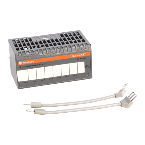
FLEX I/O-XT Digital DC Input/Output Modules
Catalog Numbers 1794-OB8EPXT, 1794-IB16XT, 1794-OB16PXT, 1794-IB10XOB6XT
Modules with an XT in the last position of the catalog number are conformally coated to meet noxious gas requirements of ISA/ANSI-71.040-1985 Class G3 Environment.
Topic
Summary of Changes
Install Your Digital DC Input/Output Module
Configure Your Module
Specifications
Summary of Changes
This publication contains the following new or updated information. This list includes substantive updates only and is not intended to reflect all changes.
Description
Updated template
Updated Environment and Enclosure
Updated Special Conditions for Safe Use
Updated UK and European Hazardous Location Approval
Updated IEC Hazardous Location Approval
Updated Specifications
Updated General Specifications
Updated Environmental Specifications
Updated Certifications
Page
1
5
8
11
Page
throughout
3
3
4
4
11
12
12
13
Advertisement
Table of Contents

Related Manuals for Rockwell Automation Allen-Bradley 1794-OB8EPXT


Summary of Contents for Rockwell Automation Allen-Bradley 1794-OB8EPXT
- Page 1 Installation Instructions Original Instructions FLEX I/O-XT Digital DC Input/Output Modules Catalog Numbers 1794-OB8EPXT, 1794-IB16XT, 1794-OB16PXT, 1794-IB10XOB6XT Modules with an XT in the last position of the catalog number are conformally coated to meet noxious gas requirements of ISA/ANSI-71.040-1985 Class G3 Environment. Topic Page Summary of Changes...
- Page 2 Indien de apparatuur wordt gebruikt op een wijze die niet is gespecificeerd door de fabrikant, dan bestaat het gevaar dat de beveiliging van de apparatuur niet goed werkt. Rockwell Automation Publication 1794-IN124B-EN-P - July 2022...
-
Page 3: Environment And Enclosure
The enclosure must be accessible only by the use of a tool. • This equipment shall be used within its specified ratings defined by Rockwell Automation. • Transient protection shall be provided that is set at a level not exceeding 140% of the peak rated voltage value at the supply terminals to the equipment. -
Page 4: Iec Hazardous Location Approval
à une utilisation en environnement de Classe I, Division 2. • If this product contains batteries, they must only be changed in • S’assurer que l’environnement est classé non dangereux avant de an area known to be nonhazardous. changer les piles. Rockwell Automation Publication 1794-IN124B-EN-P - July 2022... - Page 5 If daisychaining power to the next terminal base, connect a jumper from terminal 51 (+V DC) on this base unit to terminal 34 on the next base unit. If continuing DC common to the next base unit, connect a jumper from terminal 33 (common) on this base unit to terminal 16 on the next base unit. Rockwell Automation Publication 1794-IN124B-EN-P - July 2022...
- Page 6 Input 13 A-13 C-48 B-30 Input 14 A-14 C-49 B-31 Input 15 A-15 C-50 B-32 +V DC C-34…C-51 Common B-16…B-33 3-wire devices use input, supply and common; 2-wire devices use input and supply. Rockwell Automation Publication 1794-IN124B-EN-P - July 2022...
- Page 7 Use B-33 and C-51 for daisy-chaining to next terminal base unit. Commons Common Common Voltage Voltage Voltage Out +V In +V (1794-TB3 shown) (1794-TB3 shown) Connect V common to terminals B-16 Connect +V to terminal C-34 Rockwell Automation Publication 1794-IN124B-EN-P - July 2022...
-
Page 8: Configure Your Module
The unused lower byte in read word 1 floats during operation. Do not use this byte for fault status. See Program the 1794-OB8EPXT on page C, CR, and CF not available when used with any series 1794-ASB or 1794-ASB2 remote I/O adapter modules. Rockwell Automation Publication 1794-IN124B-EN-P - July 2022... - Page 9 Filter Time 1 0.5 ms Filter Time 2 1.0 ms Filter Time 3 2.0 ms Filter Time 4 4.0 ms Filter Time 5 8.0 ms Filter Time 6 16.0 ms Filter Time 7 32.0 ms Rockwell Automation Publication 1794-IN124B-EN-P - July 2022...
- Page 10 When you press the reset button, the fault indicator for the faulted output turns off for about 1.2 s. After the delay, the faulted output attempts to turn on. If the external condition causing the fault is corrected, the output will remain on, the fault indicator is off, and the status indicator is on. Rockwell Automation Publication 1794-IN124B-EN-P - July 2022...
-
Page 11: Specifications
No isolation between individual channels Type tested at 1365V AC for 60 s, between field side and system Type tested at 850V AC for 60 s, between field side and system Flexbus current 50 mA 30 mA Rockwell Automation Publication 1794-IN124B-EN-P - July 2022... -
Page 12: General Specifications
±2kV @ 5kHz on signal ports IEC 61000-4-5: Surge transient immunity ±1 kV line-line(DM) and ±2 kV line-earth(CM) on signal ports IEC 61000-4-6: Conducted RF immunity 10V rms with 1 kHz sine-wave 80% AM from 150 kHz…80 MHz Rockwell Automation Publication 1794-IN124B-EN-P - July 2022... - Page 13 Article 58-2 of Radio Waves Act, Clause 3 Russian Customs Union TR CU 020/2011 EMC Technical Regulation See the Product Certification link at rok.auto/certifications for Declaration of Conformity, Certificates, and other certification details. Rockwell Automation Publication 1794-IN124B-EN-P - July 2022...
-
Page 14: Rockwell Automation Support
Rockwell Otomasyon Ticaret A.Ş. Kar Plaza İş Merkezi E Blok Kat:6 34752 İçerenköy, İstanbul, Tel: +90 (216) 5698400 EEE Yönetmeliğine Uygundur Connect with us. Allen-Bradley, expanding human possibility, FactoryTalk, FLEX I/O-XT, Rockwell Automation, and TechConnect are trademarks of Rockwell Automation, Inc. Trademarks not belonging to Rockwell Automation are property of their respective companies.
Need help?
Do you have a question about the Allen-Bradley 1794-OB8EPXT and is the answer not in the manual?
Questions and answers