Advertisement
Quick Links
NCL30081LEDGEVB
3.6 W Flyback 3 LED Step
Dimmable Driver Evaluation
Board User's Manual
Overview
This documentation package covers an NCL30081 LED
driver for use in a GU10 based LED lamp. The output is
mains isolated by double insulation. Maximum input power
is 5 W. The ECA (Electronic Circuit Assembly) supports 2
versions; one step dimming and one non-dimming version.
The version is controlled through minor bill-of-material
changes. The LED current dims in 5 discrete levels
sequentially by detecting the interruption of the AC mains
briefly (about 1 s) to step the LED current down one level
until it cycles back to full current.
Modifications
The value of R
sets the final output current value along
trim
with R
. R
is for fine adjustment. The nature of the
sense
trim
open loop control makes the current adjustment somewhat
iterative based on available standard resistor values and
because of the circuit parameters that affect the output
current setting.
© Semiconductor Components Industries, LLC, 2013
March, 2013 − Rev. 0
dependent current source creates a line dependent offset on
the CS pin to account for propagation delay errors in the
peak primary current. Changing the FET or gate driver
resistor will also have some effect on the output current.
the level where power factor or harmonic current
requirements are applicable in many countries (e.g. US). In
the
IEC61000-3-2 Class C are applicable even at this low power
level. Compliance to the Class C requirements is simple with
a change of the input capacitor from 4.7 mF to 1 mF. This
change limits the input voltage operation to 200–265 V ac
because there is insufficient energy storage for the full
universal line range.
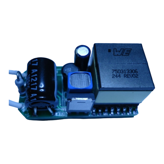
Figure 1. NCL30081LEDG Evaluation Board
1
http://onsemi.com
EVAL BOARD USER'S MANUAL
Line regulation is optimized by the selection of R
Since the input power is < 5 W maximum, this falls below
EU,
the
harmonic
. A line
lff
current
requirements
for
Publication Order Number:
EVBUM2175/D
Advertisement

Subscribe to Our Youtube Channel
Related Manuals for ON Semiconductor NCL30081


Summary of Contents for ON Semiconductor NCL30081
- Page 1 Board User's Manual http://onsemi.com EVAL BOARD USER’S MANUAL Overview This documentation package covers an NCL30081 LED Line regulation is optimized by the selection of R . A line driver for use in a GU10 based LED lamp. The output is dependent current source creates a line dependent offset on mains isolated by double insulation.
-
Page 2: Theory Of Operation
NCL30081LEDGEVB THEORY OF OPERATION Figure 3 (DCM). Figure 2 shows the basic circuit of a fly-back portrays the primary and secondary current of a converter. fly-back converter in discontinuous conduction mode Transformer bulk leak Clamping Network lump sense Figure 2. Basic Fly-back Converter Schematic During the on-time of the MOSFET, the bulk voltage V When the diode conducts, the secondary current decreases bulk... -
Page 3: Specifications
NCL30081LEDGEVB L,pk D,pk Time demag Time Figure 3. Flyback Currents and Auxiliary Winding Voltage in DCM ® At this point the Excel spreadsheet based design guide circuit will create some error on the CS pin which is adjusted will help with many of the calculations. out by proper choice of R trim A trim resistor allows for making fine adjustments to the... - Page 4 LED− 56 kW 20 W 420 pF 250 VAC Y2 leak CCbulk UFM15PL 27 mF 470 pF 250 VAC Y2 1.8 W NCL30081 51.1 kW 4.7 mF NDD02N60Z 1.10 kW trim sens 11 W 1.8 W Figure 5. Main Schematic...
- Page 5 502R29W471KV3E-****-SC Dclamp BZX100A SOD323F BZX100A,115 Dleak UFM15PL SOD123FL UFM15PL Dout UFM12PL SOD123FL UFM12PL MB6S MB6S MB6S BAS21DW5T1G SC-88A ON Semiconductor BAS21DW5T1G 1.5 mH IND-UPRIGHT-LS25 Wurth 7447462152 Qfet NDD02N60Z IPAK ON Semiconductor NDD02N60Z 0805 Yageo RC0805FR-073M01L 3.01 MW Rfuse FUSE FUSE-HAIRPIN-LS250 Littelfuse 0263.500WRT1L...
- Page 6 NCL30081LEDGEVB GERBER VIEWS Figure 6. Component Side PCB Figure 7. Component Side Silkscreen Figure 8. Solder Side PCB http://onsemi.com...
- Page 7 NCL30081LEDGEVB GERBER VIEWS (CONTINUED) Figure 9. Solder Side Silkscreen CIRCUIT BOARD FABRICATION NOTES 1. Fabricate per IPC-6011 and IPC6012. Inspect to 14. Solder mask misregistration ±0.004 in. max. IPA-A-600 Class 2 or updated standard. 15. Silkscreen shall be permanent non-conductive 2.
- Page 8 NCL30081LEDGEVB FLYBACK TRANSFORMER SPECIFICATION CUSTOMER TERMINAL RoHS LEAD(Pb)-FREE Update views to show flying leads and lead length dimension. Leads are 2″ from outside bobbin rail and 1.8″ tinned. Sn 96%, Ag 4% .500 MAX. .676 MAX. TERM. NO.’s FOR REF. ONLY [12.70] [17.17] .550 MAX.
- Page 9 NCL30081LEDGEVB ECA PICTURES CVccbulk Detected for Non-dimming Version Figure 10. Top View Figure 11. Bottom View Trim Transformer Flying Leads to Shortest Possible Length Flying Leads are Solder Strippable Flagged FL1 Figure 12. Transformer and Output Terminations http://onsemi.com...
-
Page 10: Test Procedure
NCL30081LEDGEVB TEST PROCEDURE Equipment Needed Test Connections • 1. Connect the Unit Under Test (UUT) per the test set AC Source: up in Figure 13 90−265 V ac 50/60 Hz Minimum 1 A ac capability 2. Set the AC source per the test procedure. •... - Page 11 NCL30081LEDGEVB TEST DATA Figure 14. Regulation over Line Voltage Figure 15. Efficiency over Line Voltage http://onsemi.com...
- Page 12 NCL30081LEDGEVB TEST DATA (CONTINUED) Figure 16. Power Factor over Line Voltage Figure 17. Dimming over Line Voltage http://onsemi.com...
- Page 13 NCL30081LEDGEVB TEST DATA (CONTINUED) Figure 18. Drain Voltage @ 90 V ac Figure 19. Drain Voltage @ 265 V ac http://onsemi.com...
- Page 14 NCL30081LEDGEVB TEST DATA (CONTINUED) Figure 20. Output Ripple 90 V ac 50 Hz Figure 21. Output Ripple 265 V ac 50 Hz http://onsemi.com...
- Page 15 NCL30081LEDGEVB TEST DATA (CONTINUED) Figure 22. Conducted EMI Pre-compliance 150 kHz−2 MHz Figure 23. Conducted EMI Pre-compliance 150 kHz−30 MHz http://onsemi.com...
- Page 16 NCL30081LEDGEVB APPENDIX IEC61000-3-2 Class C Compliance If the discharge lighting equipment has a built-in dimming Compliance to IEC61000-3-2 Class C (under 25 W) is not device, measurement is made only in the full load condition. possible with the universal front end architecture since input It is possible to comply with the special waveform and current does not comply with Class D requirements or the harmonic requirements of the third paragraph with a...
-
Page 17: Additional Information
onsemi, , and other names, marks, and brands are registered and/or common law trademarks of Semiconductor Components Industries, LLC dba “onsemi” or its affiliates and/or subsidiaries in the United States and/or other countries. onsemi owns the rights to a number of patents, trademarks, copyrights, trade secrets, and other intellectual property. A listing of onsemi’s product/patent coverage may be accessed at www.onsemi.com/site/pdf/Patent−Marking.pdf.
Need help?
Do you have a question about the NCL30081 and is the answer not in the manual?
Questions and answers