
Subscribe to Our Youtube Channel
Related Manuals for THORLABS APD440A


Summary of Contents for THORLABS APD440A
- Page 1 Adjustable Gain Avalanche Photodetectors APD440A and APD440A2 Operation Manual 2020...
- Page 2 Version: Date: 21-Feb-2020 Copyright © 2020 Thorlabs...
-
Page 3: Table Of Contents
5.6 Drawings 5.7 Fiber Coupling onto Small Detector Area 5.8 Safety 5.9 Manufacturer Address 5.10 Return of Devices 5.11 Certifications and Compliances 5.12 Warranty 5.13 Copyright and Exclusion of Liability 5.14 List of Acronyms 5.15 Thorlabs Worldwide Contacts and WEEE policy... - Page 4 Paragraphs preceded by this symbol explain hazards that could damage the instrument and the connected equipment or may cause loss of data. Note This manual also contains "NOTES" and "HINTS" written in this form. Please read this advice carefully! © 2020 Thorlabs...
-
Page 5: General Information
The detector housing can be integrated in optical setups using convenient 8-32 and M4 combi- thread mounting holes that are compatible with both imperial and metric threading. The housing accommodates Thorlabs' SM05 (0.535"-40) and SM1 (1.035"-40) threaded adap- ters and accessories. This allows convenient mounting of external optics, light filters, and aper- tures. -
Page 6: Getting Started
Adjust the power supply accordingly to 100 VAC, 120 VAC or 230 VAC. Attention Wrong settings for the mains voltage may damage the power supply. Note If you prefer to use your own power supply, please ask Thorlabs for an appropriate power connector cable. © 2020 Thorlabs... -
Page 7: Operating Instruction
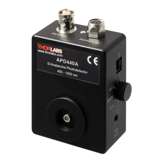
3 Operating Instruction 3 Operating Instruction 3.1 Operating Elements APD440A and APD440A2 have identical operating elements. Here shown is the APD440A, representing both APD440A and APD440A2. 3.2 Mounting Housing The APD440x is housed in a rugged, shielded, 74.5 mm x 56.1 mm x 27.4 mm aluminum en- closure. -
Page 8: Operation
Thorlabs’ SM05 (0.535"-40) threads and SM1 (1.035"-40) threads that are com- patible with any number of Thorlabs 1” and ½” threaded accessories. This also allows conveni- ent mounting of lens tubes or cage systems. For accessories, please visit our website or con-... -
Page 9: Recommendations
Electrostatic coupling of electrical noise associated with ground loops can be critical. In most cases an electrically isolated post (see Thorlabs parts TRE or TRE/M) will suppress electrical noise coupling. Electrical noise sources should always be identified and the distance to the Avalanche Photodetector should be increased. -
Page 10: Optical Input
M-factor that is equivalent to a gain variation. 3.5.1 Optical Input The APD440A uses a Silicon Avalanche Photodiode with a detector active area diameter of 1.0 mm, operating from 400 to 1000 nm and the APD440A2 uses an UV-enhanced Silicon Avalanche Photodiode with a detector active area diameter of 1.0 mm, operating from... -
Page 11: Temperature Compensation
(l) for a given wavelength can be read from the typical spectral responsivity curves (see · Appendix · The M-factor (gain) adjustment range is 5 - 50 (APD440A2) and 10 - 100 (APD440A) at 23°C ambient temperature. · The amplifier’s transimpedance gain G is 50 MV/A (High-Z termination) and 25 MV/A (50 W). -
Page 12: Maintenance And Service
The unit does not need regular maintenance by the user. It does not contain any modules and/or components that could be repaired by the user himself. If a malfunction occurs, please contact Thorlabs for return instructions. WARNING Do not remove covers! Dangerous deadly high voltage! © 2020 Thorlabs... -
Page 13: Appendix
Conversion Gain at the Peak Responsivity Wavelength. The Conversion Gain is a product of the Transimpedance Gain and the Responsivity for a given M factor and wavelength. At Maximum Gain Setting. For more information on how NEP is calculated, please see Thorlabs' Noise Equivalent Power White Paper. -
Page 14: Typical Responsivity Curves
APD440x 5.2 Typical Responsivity Curves Typical Detector Responsivity APD440A; M = 100 Typical Detector Responsivity APD440A2; M = 50 © 2020 Thorlabs... -
Page 15: Typical Output Frequency Response
For this measurement a test signal, generated by an optical transmitter, was fiber-coupled to the Avalanche Photodetector. The Output Frequency Response was measured using an optical network analyzer. Typical Output Frequency Response APD440A Typical Output Frequency Response APD440A2 © 2020 Thorlabs... -
Page 16: Typical Spectral Noise
1 kHz, video bandwidth 1 kHz). The optical input of the detector was blocked. The black curve ("Reference") was measured with the same setup and the detector switched off, i.e., it represents the measurement system’s noise floor. © 2020 Thorlabs... -
Page 17: Typical M Factor Temperature Dependency
5 Appendix 5.5 Typical M Factor Temperature Dependency © 2020 Thorlabs... -
Page 18: Drawings
APD440x 5.6 Drawings The below drawings show the APD440x without the SM1 coupler. Please refer to the APD440A dimensions for APD440A2. The dimensions of these products are identical. © 2020 Thorlabs... -
Page 19: Fiber Coupling Onto Small Detector Area
Below is a possible arrangement, shown on the example of the APD430A2/M. The arrangement is identical for all Thorlabs Avalance Photodiodes. The assembly in front of the detector comprises of a fiber collimator (dependent on fiber), a lens tube collimator adapter (AD11F or AD12F, dependent on collimator), a SM1L1 lens tube with aspheric lens inside (not visible above) and a LM1XY X-Y translation mount. -
Page 20: Safety
If necessary, ask for replacement packaging. Refer servicing to qualified personnel! Only with written consent from Thorlabs may changes to single components be made or com- ponents not supplied by Thorlabs be used. All modules must only be operated with duly shielded connection cables. -
Page 21: Certifications And Compliances
5 Appendix 5.11 Certifications and Compliances © 2020 Thorlabs... -
Page 22: Warranty
Thorlabs warrants material and production of the APD440x for a period of 24 months starting with the date of shipment. During this warranty period Thorlabs will see to defaults by repair or by exchange if these are entitled to warranty. -
Page 23: List Of Acronyms
5 Appendix 5.14 List of Acronyms Acronyms Alternating Current Avalanche Photo Diode Continuous Wave Direct Current Light Emitting Diode Noise Equivalent Power Radio Frequencies Silicon Signal-to-Noise Ratio Ultraviolet © 2020 Thorlabs... -
Page 24: Thorlabs Worldwide Contacts And Weee Policy
Contact Thorlabs for more information. Waste treat- ment is your own responsibility. “End of life” units must be returned to Thorlabs or handed to a company specializing in waste recovery. Do not dispose of the unit in a litter bin or at a public waste disposal site. - Page 25 www.thorlabs.com...
Need help?
Do you have a question about the APD440A and is the answer not in the manual?
Questions and answers