Table of Contents
Advertisement
Quick Links
Advertisement
Table of Contents

Related Manuals for THORLABS PDA30B


Summary of Contents for THORLABS PDA30B
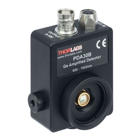
- Page 1 PDA30B Ge Switchable Gain Detector User Guide...
-
Page 2: Table Of Contents
Troubleshooting ..............7 Chapter 6 Specifications ..............8 6.1. Response Curve ............10 6.2. Mechanical Drawing ..........11 Chapter 7 Certificate of Conformance ..........12 Chapter 8 Regulatory ................ 13 Chapter 9 Thorlabs Worldwide Contacts ........14 Page 1 August 2, 2012... -
Page 3: Chapter 1 Warning Symbol Definitions
Chapter 1: Warning Symbol Definitions Chapter 1 Warning Symbol Definitions Below is a list of warning symbols you may encounter in this manual or on your device. Symbol Description Direct Current Alternating Current Both Direct and Alternating Current Earth Ground Terminal Protective Conductor Terminal Frame or chassis Terminal Equipotentiality... -
Page 4: Chapter 2 Description
~135mA of output current. This will damage the output driver of the PDA30B. Power the PDA30B on using the power switch located on the top side of the unit. Install any desired filters, optics, adapters, or fiber adapters to the input aperture. -
Page 5: Chapter 4 Operation
Failure to do so may cause damage to the diode and or the fiber. An easy way to accomplish this is to install a SM1RR retaining ring (included with the PDA30B) inside the 1" threaded coupler before installing the fiber adapter Chapter 4 Operation 4.1. -
Page 6: Dark Current
InGaAs Biased Detector 4.3. Dark Current Dark current is leakage current which flows when a bias voltage is applied to a photodiode. The PDA with Transimpedance Amplifier does control the dark current flowing out. Looking at the figure 1 above, it can be noted that Point B is held at a “Virtual Ground”... -
Page 7: Gain Adjustment
> 5 kΩ) and 1 volts for 50 Ω loads. Adjust the gain so that the measured Load signal level out of the PDA30B is below 2 volts (1 volts with a 50 Ω load) to avoid saturation. For low terminating resistors, <5 kΩ or 1% error, an additional factor needs to be included in the above formula. -
Page 8: Chapter 5 Troubleshooting
InGaAs Biased Detector Chapter 5 Troubleshooting Problem Suggested Solutions There is no signal response. Verify that the power is switched on and all connections are secure. Verify the proper terminating resistor is installed if using a Voltage measurement device. Verify that the optical signal wavelength is within the specified wavelength range. -
Page 9: Chapter 6 Specifications
All measurements performed with a 50 Ω load unless stated otherwise. The PDA30B has a 50 Ω series terminator resistor (i.e. in series with amplifier output). This forms a voltage divider with any load impedance (e.g. 50 Ω load divides signal in half). - Page 10 AC – DC Converter Input Power 100-200 VAC (50 to 60Hz) 220-240 VAC (50 to 60 Hz) Although the power supply is rated for 31W the PDA30B actual usage is <5W over the full operating range. Page 9 August 2, 2012...
-
Page 11: Response Curve
Chapter 6: Specifications 6.1. Response Curve DET30B Spectral Response 1000 1200 1400 1600 1800 Wavelength (nm) 23155-D02, Rev A Page 10... -
Page 12: Mechanical Drawing
InGaAs Biased Detector 6.2. Mechanical Drawing Please visit the web for a more detailed mechanical drawing. Power Supply Connector Indicator Power 0.08" (1.9 mm) Output BNC Detail A Scale 2:1 0.88" (22.4 mm) 1.035"-40 External Threading Mates with SM1 Line 2.06"... -
Page 13: Chapter 7 Certificate Of Conformance
Chapter 7: Certificate of Conformance Chapter 7 Certificate of Conformance 23155-D02, Rev A Page 12... -
Page 14: Chapter 8 Regulatory
8.1. Waste Treatment is Your Own Responsibility If you do not return an “end of life” unit to Thorlabs, you must hand it to a company specialized in waste recovery. Do not dispose of the unit in a litter bin or at a public waste disposal site. -
Page 15: Chapter 9 Thorlabs Worldwide Contacts
Chapter 9: Thorlabs Worldwide Contacts Chapter 9 Thorlabs Worldwide Contacts USA, Canada, and South America Thorlabs, Inc. 56 Sparta Avenue Newton, NJ 07860 Tel: 973-300-3000 Fax: 973-300-3600 www.thorlabs.com www.thorlabs.us (West Coast) Email: sales@thorlabs.com Support: techsupport@thorlabs.com Europe UK and Ireland Thorlabs GmbH Thorlabs Ltd. - Page 16 www.th h orlabs.com m...
Need help?
Do you have a question about the PDA30B and is the answer not in the manual?
Questions and answers