Table of Contents
Advertisement
Quick Links
Advertisement
Table of Contents

Related Manuals for THORLABS PDB570C


Summary of Contents for THORLABS PDB570C
- Page 1 Balanced Amplified Photodetectors PDB570C Operation Manual 2019...
- Page 2 Version: Date: 08-Apr-2019 Item No.: M0009-510-826 Copyright © 2019 Thorlabs...
-
Page 3: Table Of Contents
3.8 Recommendations 4 Maintenance and Service 5 Appendix 5.1 Technical Data 5.2 Individual Diagrams PDB570C 5.3 Dimensions 5.4 Certifications and Compliances 5.5 Warranty 5.6 Copyright and Exclusion of Reliability 5.7 Thorlabs 'End of Life' Policy (WEEE) 5.8 Thorlabs Worldwide Contacts... -
Page 4: Foreword
Paragraphs preceded by this symbol explain hazards that could damage the instrument and the connected equipment or may cause loss of data. Note This manual also contains "NOTES" and "HINTS" written in this form. Please read this advice carefully! © 2019 Thorlabs... -
Page 5: General Information
Distinguished properties of the PDB570C are it's exceptionally low NEP, optical gain control and auto-balancing function with a variable closed loop control velocity. -
Page 6: Installation
PDB570C 2 Installation This section is intended to provide information how to set up quickly the PDB570C Balanced Amplified Photodetectors. More details and advanced features are described in further sec- tions. 2.1 Parts List Inspect the shipping container for damage. - Page 7 Turn the power switch of the power supply to "I". The green LED next to the DC input con- nector indicates correct power supply. Connect the optical source(s) to the optical input(s). Please note that the PDB570C is de- ·...
-
Page 8: Operating Instruction
In auto-balanced mode, a control output allows to monitor the control loop signal. The ve- locity of the control loop is adjustable. The PDB570C is powered by an external linear power supply (±12 V, 250 mA - included) via a PICO M8 power connector. -
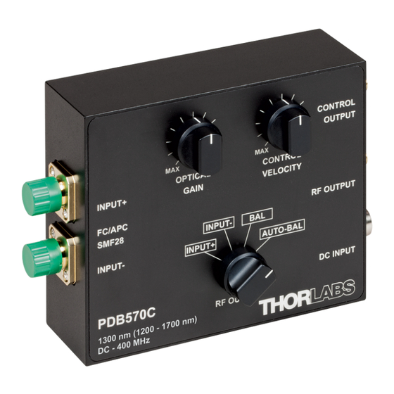
Page 9: Operating Elements
Switch RF OUTPUT Operating mode selector 3.3 Operating Modes The PDB570C offers three different operating modes: 3.3.1 Single Detector Mode In single detector mode, both inputs can be connected to a signal source. Set the mode switch to INPUT+ or INPUT- depending on what input should be monitored at RF OUTPUT. -
Page 10: Balanced Mode
OPTICAL GAIN control affects only INPUT-, while INPUT+ is controlled by the control loop sig- nal for power balance. An outstanding feature of the PDB570C is the gain control to lower as well as to higher values. That means, that it's not significant which of the two input signals has the higher level. -
Page 11: Optical Inputs
Appendix and the subsequent specifications and diagrams. The PDB570C can be used in balanced mode (both inputs are illuminated) as well as in single detector mode. In order to avoid saturation, the output signal level should not exceed the max. RF OUTPUT voltage swing! This can be achieved by reducing the optical input power or the optical gain set- ting. -
Page 12: Mounting
3.6 Mounting The PDB570C is housed in a rugged shielded aluminum enclosure. For post mounting an adapter can be attached to the bottom or side surface using four M2x8 screws (see below). This adapter supports #8-32 as well as M4 post mounts. The M4 tread is marked. -
Page 13: Cmrr And Frequency Response
Common Mode Rejection Ratio (CMRR). In the setup as de- scribed below, the Device under Test (DuT) - here a PDB570C - is tested for CMRR. A com- mon mode signal is generated, which is canceled out when the amplifier is in balanced or auto- balanced mode. -
Page 14: Recommendations
Thorlabs PDB570C Balanced Amplified Photodetectors can eliminate noise sources to allow precise measurements. The PDB570C is designed to be used in a fiber based setup: one op- tical path for measurement and one invariant reference path. If set up properly, the PDB570C can reduce common mode noise for more than 30 dB over the specified frequency range. - Page 15 Noise Factor (ENF). It describes the statistical noise that is inherent with the stochastic APD multiplication process. · The non-linearity of the used APD leads to a decrease of the PDB570C conversion gain, par- ticularly at high optical gain and high input power levels: Above diagram shows the dependency of the RF OUTPUT voltage of optical input power.
- Page 16 · absolute input power level · modulation depth of of the disturbance signal This means, that the loop velocity varies depending on above stated factors. For this reason, the CONTROL VELOCITY is not graduated in bandwidth values. © 2019 Thorlabs...
-
Page 17: Maintenance And Service
Attention To avoid damage to the instrument, do not expose it to spray, liquids or solvents! To clean the PDB570C housing, use a damp cloth. Do not soak the unit in water or use solvent based cleaners. © 2019 Thorlabs... -
Page 18: Appendix
The electrical noise is independent of the optical gain setting! Typical frequency response curves are measured using the setup described in section "CMRR and Frequency Response" © 2019 Thorlabs... -
Page 19: Technical Data
Values for transimpedance and conversion gain are lossless gain values, i.e., losses introduced by FC/APC con- nectors (typically 0.15 to 0.35 dB) are not considered. All technical data are valid at 23 ± 5°C and 45 ± 15% rel. humidity (non condensing) © 2019 Thorlabs... -
Page 20: Individual Diagrams Pdb570C
PDB570C 5.2 Individual Diagrams PDB570C PDB570C - Typical Detector Responsivity PDB570C Typical RF Output Frequency Response (Single Detector Mode, Gain M=5) © 2019 Thorlabs... - Page 21 PDB570C - Optical Gain Variation in Single Detector mode PDB570C Frequency Response in BAL and AUTO BAL modes Above diagram shows the PDB570C frequency response in balanced and auto-balanced modes. For these measurements, the two input signals were not exactly balanced to show the...
- Page 22 PDB570C improvement of CMRR when switching over to AUTO BAL mode. The curves for INPUT+ and INPUT- were taken in BAL mode with only one input connected. PDB570C Spectral Noise © 2019 Thorlabs...
-
Page 23: Dimensions
5 Appendix 5.3 Dimensions PDB570C Mechanical Drawing © 2019 Thorlabs... -
Page 24: Certifications And Compliances
Class III equipment according to IEC 60950-1:2005 Compliance demonstrated using high-quality shielded interface cables shorter than or equal to 3 meters. Emissions, which exceed the levels required by these standards, may occur when this equipment is connected to a test object. © 2019 Thorlabs... -
Page 25: Warranty
Thorlabs warrants material and production of the PDB570C for a period of 24 months starting with the date of shipment. During this warranty period Thorlabs will see to defaults by repair or by exchange if these are entitled to warranty. -
Page 26: Thorlabs 'End Of Life' Policy (Weee)
Waste treatment on your own responsibility If you do not return an “end of life” unit to Thorlabs, you must hand it to a company specialized in waste recovery. Do not dispose of the unit in a litter bin or at a public waste disposal site. -
Page 27: Thorlabs Worldwide Contacts
Email: europe@thorlabs.com Email: scandinavia@thorlabs.com France Brazil Thorlabs SAS Thorlabs Vendas de Fotônicos Ltda. 109, rue des Côtes Rua Riachuelo, 171 78600 Maisons-Laffitte São Carlos, SP 13560-110 France Brazil Tel: +33-970 444 844 Tel: +55-16-3413 7062 Fax: +33-825 744 800 Fax: +55-16-3413 7064 www.thorlabs.com... - Page 28 www.thorlabs.com...
Need help?
Do you have a question about the PDB570C and is the answer not in the manual?
Questions and answers