Table of Contents
Advertisement
Quick Links
Advertisement
Table of Contents

Related Manuals for THORLABS APD450C


Summary of Contents for THORLABS APD450C
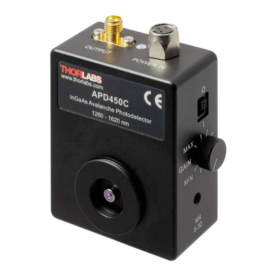
- Page 1 Adjustable Gain Avalanche Photodetectors APD450C Operation Manual 2020...
- Page 2 Version: Date: 04-Jun-2020 Copyright © 2020 Thorlabs...
-
Page 3: Table Of Contents
5.6 Drawings 5.7 Fiber Coupling onto Small Detector Area 5.8 Safety 5.9 Manufacturer Address 5.10 Return of Devices 5.11 Certifications and Compliances 5.12 Warranty 5.13 Copyright and Exclusion of Liability 5.14 List of Acronyms 5.15 Thorlabs Worldwide Contacts and WEEE policy... - Page 4 Paragraphs preceded by this symbol explain hazards that could damage the instrument and the connected equipment or may cause loss of data. Note This manual also contains "NOTES" and "HINTS" written in this form. Please read this advice carefully! © 2020 Thorlabs...
-
Page 5: General Information
For accessories, please visit our website or contact Thorlabs The APD450C Avalanche Photodetectors are powered by the included external power supply LDS12B (±12 VDC, 250 mA) via a PICO M8 power connector. The appropriate input voltage (100 VAC, 120 VAC, 230 VAC) can be selected with a switch on the... -
Page 6: Getting Started
If the shipping container seems to be damaged, keep it until you have inspected the contents and you have inspected the APD450C mechanically and electrically. Verify that you have received the following items within the package: 1. -
Page 7: Operating Instruction
3.1 Operating Elements 3.2 Mounting Housing The APD450C is housed in a rugged, shielded, 72.0 mm x 56.3 mm x 27.4 mm aluminum en- closure. Mounting APD450C on an Optical Table Mount the APD450C on an optical post by using either of the three tapped mounting holes on the sides and bottom. -
Page 8: Operation
Please note that a 50 W impedance device should be used for best RF performance. · Switch on the power supply. · Move the power slider to I to turn on the APD450C. The green LED on the APD450C indi- cates the correct power supply. -
Page 9: Recommendations
· Impact of Temperature o The M-factor is factory set at 23°C ambient temperature. The APD450C is operated at an internal reverse bias voltage that is temperature-compensated. Therefore, the actual M factor will remain nearly constant within the specified ambient temperature range of (23±5)°C. -
Page 10: Optical Input
Avalanche Photodetectors because the housing is compatible with any number of Thorlabs 1” and ½” threaded accessories. For detectors with smaller active areas, as it is the case for APD450C, it is recommended to fo- cus the optical signal out of the fiber onto the detector. -
Page 11: Temperature Compensation
· Appendix · The M-factor (gain) adjustment range for APD450C is 2 to 10 at 23°C ambient temperature. · The amplifier’s transimpedance gain G is 5 kV/A at 50 W. The maximum output voltage of the APD450C is 2.0 V into 50 W. Depending on the Â(l) -
Page 12: Maintenance And Service
APD450C 4 Maintenance and Service Protect the APD450C from adverse weather conditions. The APD450C is not water resistant. Attention To avoid damage to the instrument, do not expose it to spray, liquids or solvents! The unit does not need regular maintenance by the user. It does not contain any modules and/or components that could be repaired by the user himself. -
Page 13: Appendix
The Conversion Gain is product of the Transimpedance Gain and the Responsivity for a given M factor and wavelength. At Maximum Gain Setting. For more information on how NEP is calculated, please see Thorlabs' Noise Equivalent Power White Paper. Non-condensing... -
Page 14: Typical Responsivity Curves
APD450C 5.2 Typical Responsivity Curves Typical Detector Responsivity APD450C; M = 10 5.3 Typical Output Frequency Response Effect of the gain settings on the respective Typical Output Frequency Response. For this measurement a test signal, generated by an optical transmitter, was fiber-coupled to the Avalanche Photodetector. -
Page 15: Typical Spectral Noise
1 kHz, video bandwidth 1 kHz). The optical input of the detector was blocked. The black curve ("Reference") was measured with the same setup and the detector switched off, i.e., it represents the measurement system’s noise floor. 5.5 Typical M Factor Temperature Dependency © 2020 Thorlabs... -
Page 16: Drawings
APD450C 5.6 Drawings The below drawings show the APD450C without the SM1 coupler. © 2020 Thorlabs... -
Page 17: Fiber Coupling Onto Small Detector Area
The beam out of the fiber is collimated (transferred into a nearly parallel beam) and afterwards focused by the aspheric lens. In the case of the APD450C, the beam should be focused onto the focal plane of the integrated ball lens. The X-Y translation mount allows the focused beam to be aligned with the center of the sensor. -
Page 18: Safety
If necessary, ask for replacement packaging. Refer servicing to qualified personnel! Only with written consent from Thorlabs may changes to single components be made or com- ponents not supplied by Thorlabs be used. All modules must only be operated with duly shielded connection cables. -
Page 19: Certifications And Compliances
5 Appendix 5.11 Certifications and Compliances © 2020 Thorlabs... -
Page 20: Warranty
Thorlabs warrants material and production of the APD450C for a period of 24 months starting with the date of shipment. During this warranty period Thorlabs will see to defaults by repair or by exchange if these are entitled to warranty. -
Page 21: List Of Acronyms
5 Appendix 5.14 List of Acronyms Acronyms Alternating Current Avalanche Photo Diode Continuous Wave Direct Current Light Emitting Diode Noise Equivalent Power Radio Frequencies InGaAs Indiumgalliumarsenide Signal-to-Noise Ratio Ultraviolet © 2020 Thorlabs... -
Page 22: Thorlabs Worldwide Contacts And Weee Policy
Contact Thorlabs for more information. Waste treat- ment is your own responsibility. “End of life” units must be returned to Thorlabs or handed to a company specializing in waste recovery. Do not dispose of the unit in a litter bin or at a public waste disposal site. - Page 23 www.thorlabs.com...
Need help?
Do you have a question about the APD450C and is the answer not in the manual?
Questions and answers