Table of Contents
Advertisement
Quick Links
Advertisement
Table of Contents

Related Manuals for THORLABS DET25K2


Summary of Contents for THORLABS DET25K2
- Page 1 DET25K2 GaP Biased Detector User Guide...
-
Page 2: Table Of Contents
7.1. Response Curve ............ 13 7.2. Mechanical Drawing .......... 14 Chapter 8 Certificate of Conformance ..........15 Chapter 9 Regulatory ................ 16 Chapter 10 Thorlabs Worldwide Contacts ........17 Rev A, December 27, 2017 Page 1... -
Page 3: Chapter 1 Warning Symbol Definitions
GaP Biased Detector Chapter 1: Warning Symbol Definitions Chapter 1 Warning Symbol Definitions Below is a list of warning symbols you may encounter in this manual or on your device. Symbol Description Direct Current Alternating Current Both Direct and Alternating Current Earth Ground Terminal Protective Conductor Terminal Frame or chassis Terminal... -
Page 4: Chapter 2 Description
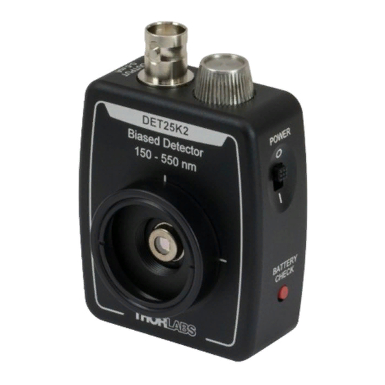
Chapter 2: Description Chapter 2 Description The Thorlabs DET25K2 is a biased, Gallium Phosphide (GaP) detector designed for detection of light signals ranging from 150 nm to 550 nm. The unit comes complete with a photodiode and an internal 12 V bias battery enclosed in rugged aluminum housing. -
Page 5: Chapter 3 Setup
See Chapter 4, page 7 to determine resistor values. Thorlabs sells a 50 Ω terminator (T4119) for best frequency performance and a variable terminator (VT2) for output voltage flexibility. -
Page 6: Chapter 4 Operation
Depicted in Figure 1 is a junction photodiode model with basic discrete components to help visualize the main characteristics and gain a better understanding of the operation of Thorlabs' photodiodes. Figure 1 Photodiode Model 4.2. -
Page 7: Dark Current
Please note that sensitivity values in the table are typical values; Thorlabs offers photodetectors with sensitivity ranges that vary from those shown below. Rev A, December 27, 2017... -
Page 8: Junction Capacitance
GaP Biased Detector Chapter 4: Operation Dark Sensitivity Material Speed Cost Current (nm) Silicon (Si) High 400 – 1000 Germanium (Ge) High 900 – 1600 Gallium Phosphide (GaP) High 150 – 550 Indium Gallium Arsenide High 800 – 1800 (InGaAs) Extended Range: Indium High High... -
Page 9: Terminating Resistance
GaP Biased Detector Chapter 4: Operation 2 0.35 4.7. Terminating Resistance A load resistance is used to convert the generated photocurrent into a voltage ) for viewing on a voltage reading device, e.g., an oscilloscope. Depending on the type of the photodiode, load resistance can affect the response speed. -
Page 10: Battery Replacement
4.11. Battery Replacement Thorlabs delivers each DET with an A23 12 V battery. This battery is readily available at most retail stores, as well as through Thorlabs. The battery supplied will deliver about 40 hours with a 1 mA load, roughly equivalent to a continuous 1.5 mW light source with responsivity 0.6 A/W... -
Page 11: Chapter 5 Common Operating Circuits
GaP Biased Detector Chapter 5: Common Operating Circuits Chapter 5 Common Operating Circuits Figure 2 Basic DET Circuit The DET Series Detectors are designed according the circuit depicted above. The detector is reverse biased to produce a linear response with applied input light. - Page 12 GaP Biased Detector Chapter 5: Common Operating Circuits One can also use a photodetector with an amplifier for the purpose of achieving high gain. The user can choose whether to operate in Photovoltaic of Photoconductive modes. There are a few benefits of choosing this active circuit: ...
-
Page 13: Chapter 6 Troubleshooting
GaP Biased Detector Chapter 6: Troubleshooting Chapter 6 Troubleshooting Problem Suggested Solutions There is no signal response. Verify that the power is switched on and all connections are secure. Verify the proper terminating resistor is installed if using a Voltage measurement device. Verify that the optical signal wavelength is within the specified wavelength range. -
Page 14: Chapter 7 Specifications
GaP Biased Detector Chapter 7: Specifications Chapter 7 Specifications All measurements performed at 25 °C ambient temperature, unless stated otherwise. Electrical Specifications Detector Active Area 2.2 mm x 2.2 mm (4.8 mm Wavelength Range λ 150 to 550 nm Peak Wavelength λ... -
Page 15: Response Curve
GaP Biased Detector Chapter 7: Specifications 7.1. Response Curve Biased GaP Detector Responsivity 0.12 0.10 0.08 0.06 0.04 DET25K2 0.02 0.00 Wavelength (nm) Rev A, December 27, 2017 Page 13... -
Page 16: Mechanical Drawing
GaP Biased Detector Chapter 7: Specifications 7.2. Mechanical Drawing Visit the web for a more detailed mechanical drawing. Page 14 TTN134134-D02... -
Page 17: Chapter 8 Certificate Of Conformance
GaP Biased Detector Chapter 8: Certificate of Conformance Chapter 8 Certificate of Conformance Rev A, December 27, 2017 Page 15... -
Page 18: Chapter 9 Regulatory
Waste Treatment is Your Own Responsibility If you do not return an “end of life” unit to Thorlabs, you must hand it to a company specialized in waste recovery. Do not dispose of the unit in a litter bin or at a public waste disposal site.
Need help?
Do you have a question about the DET25K2 and is the answer not in the manual?
Questions and answers