Table of Contents
Advertisement
Advertisement
Table of Contents

Related Manuals for THORLABS PDA36A2


Summary of Contents for THORLABS PDA36A2
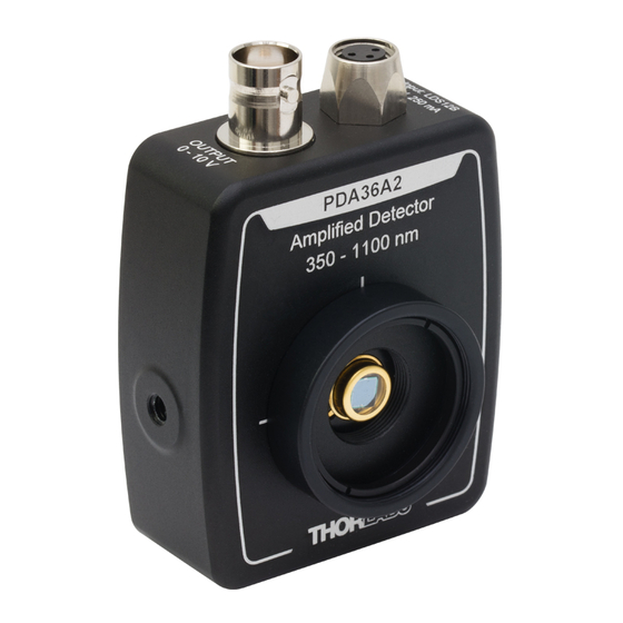
- Page 1 PDA36A2 Si Switchable Gain Detector User Guide...
-
Page 2: Table Of Contents
6.1. Response Curve.............. 9 6.2. Mechanical Drawing ............ 10 Chapter 7 Certificate of Conformance ........... 11 Chapter 8 Regulatory ............... 12 8.1. Waste Treatment is Your Own Responsibility .... 12 8.2. Ecological Background .......... 12 Chapter 9 Thorlabs Worldwide Contacts........13 ... -
Page 3: Chapter 1 Warning Symbol Definitions
Si Switchable Gain Detector Chapter 1: Warning Symbol Definitions Chapter 1 Warning Symbol Definitions Below is a list of warning symbols you may encounter in this manual or on your device. Symbol Description Direct Current Alternating Current Both Direct and Alternating Current Earth Ground Terminal Protective Conductor Terminal Frame or chassis Terminal... -
Page 4: Chapter 2 Description
10 dB steps. A buffered output drives 50 Ω load impedances up to 5 V. The PDA36A2 housing includes a removable threaded coupler (SM1T1) and retainer ring (SM1RR) that is compatible with any number of Thorlabs 1"... -
Page 5: Chapter 3 Setup
Attach a 50 Ω coax cable (i.e. RG-58U) to the output of the PDA. When running cable lengths longer than 12" we recommend terminating the opposite end of the coax with a 50 Ω resistor (Thorlabs p/n T4119) for maximum performance. Connect the remaining end to a measurement device such as an oscilloscope or high speed DAQ card. -
Page 6: Chapter 4 Operation
Chapter 4 Operation 4.1. Theory of Operation Thorlabs PDA series are ideal for measuring both pulsed and CW light sources. The PDA36A2 includes a reverse-biased PIN photo diode, mated to a switchable gain transimpedance amplifier, and packaged in a rugged housing. -
Page 7: Bandwidth And Response
The maximum output of the PDA36A2 is 10 V for high impedance loads (i.e. RLoad > 5 kΩ) and 5 V for 50 Ω loads. Adjust the gain so that the measured signal level out of the PDA36A2 is below 10 V (5 V with a 50 Ω load) to avoid saturation. -
Page 8: Chapter 5 Troubleshooting
Si Switchable Gain Detector Chapter 5: Troubleshooting Chapter 5 Troubleshooting Problem Suggested Solutions Verify that the power is switched on and all connections are secure. Verify the proper terminating resistor is installed if using a Voltage measurement device. There is no signal response. Verify that the optical signal wavelength is within the specified wavelength range. -
Page 9: Chapter 6 Specifications
±10 mV (Max) ±12 mV (Max) The PDA36A2 has a 50 Ω series terminator resistor (i.e. in series with amplifier output). This forms a voltage divider with any load impedance (e.g. 50 Ω load divides signal in half). Tested at 650 nm wavelength. For NIR wavelengths, the rise time of the photodiode element will become slower which may limit the effective bandwidth of the amplified detector. - Page 10 Measured from the active area to the start of the threads on the housing body. The detector active area surface is flush with the front of the housing body. Although the power supply is rated for 31 W the PDA36A2 actual usage is <5 W over the full operating range.
-
Page 11: Response Curve
Si Switchable Gain Detector Chapter 6: Specifications 6.1. Response Curve PDA36A2 Responsivity 1000 1100 Wavelength (nm) Rev A, December 27, 2017 Page 9... -
Page 12: Mechanical Drawing
Si Switchable Gain Detector Chapter 6: Specifications 6.2. Mechanical Drawing Page 10 TTN135069-D02... -
Page 13: Chapter 7 Certificate Of Conformance
Si Switchable Gain Detector Chapter 7: Certificate of Conformance Chapter 7 Certificate of Conformance Rev A, December 27, 2017 Page 11... -
Page 14: Chapter 8 Regulatory
Waste Treatment is Your Own Responsibility If you do not return an “end of life” unit to Thorlabs, you must hand it to a company specialized in waste recovery. Do not dispose of the unit in a litter bin or at a public waste disposal site. -
Page 15: Chapter 9 Thorlabs Worldwide Contacts
Fax: +46-31-703-40-45 www.thorlabs.de www.thorlabs.com Email: europe@thorlabs.com Email: scandinavia@thorlabs.com France Brazil Thorlabs SAS Thorlabs Vendas de Fotônicos Ltda. 109, rue des Côtes Rua Riachuelo, 171 78600 Maisons-Laffitte São Carlos, SP 13560-110 France Brazil Tel: +33 (0) 970 444 844 Tel: +55-16-3413 7062... - Page 16 www.thorlabs.com...
Need help?
Do you have a question about the PDA36A2 and is the answer not in the manual?
Questions and answers