Advertisement
Quick Links
June, 2021
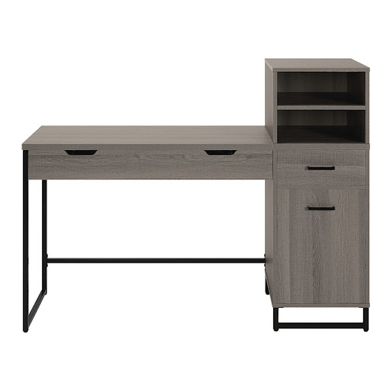
HGN784
HAGNEY LANE WORK SMART
SIT-TO-STAND DESK
®
*PATENT PENDING
Assembly Instructions - Important:
Carefully unpack and identify each component before attempting to assemble. Refer to parts list. Please take care when
assembling the unit and always set the parts on a clean, soft surface. If you require any assistance with assembly, parts or
information on other products, please visit our website: www.officestar.net or call or write us.
Advertisement

Related Manuals for OSP Home Furnishings HAGNEY LANE WORK SMART HGN784


Summary of Contents for OSP Home Furnishings HAGNEY LANE WORK SMART HGN784
- Page 1 June, 2021 HGN784 HAGNEY LANE WORK SMART SIT-TO-STAND DESK ® *PATENT PENDING Assembly Instructions - Important: Carefully unpack and identify each component before attempting to assemble. Refer to parts list. Please take care when assembling the unit and always set the parts on a clean, soft surface. If you require any assistance with assembly, parts or information on other products, please visit our website: www.officestar.net or call or write us.
- Page 2 STOP: Read these instructions carefully and keep with the product for future reference. If this product is passed on to a third party, then these instructions must be included. When using this product, basic safety precautions should always be followed to reduce the risk of injury Including the following: • A competent adult must assemble this product • Keep children and pets away while assembling this product...
- Page 3 Monday through Friday 8:00 a.m. - 3:30 p.m. Pacific Time. To make a warranty claim, contact Parts Department. Provide model number, proof of purchase, description of the problem and obtain return authorization. At its option OSP Home Furnishings will: (a) Supply compatible ®...
- Page 4 PARTS (A) Desk Top (1 PC) (B) Right Shelf (1 PC) (D) Upper Side Panel (2 PCS) (C) Right Top Panel (1 PC) (F) Left Lower Side Panel (1 PC) (E) Left Frame (1 PC) (H) Bottom Panel (1 PC) (G) Right Lower Side Panel (1 PC) (J) Adjustable Shelf (1 PC) (I) Upper Shelf (1 PC)
-
Page 5: Hardware List
PARTS (M) Back Panel (1 PC) (N) Drawer Front Panel (1 PC) (P) Drawer Right Side panel (1 PC) (O) Drawer Left Side Panel (1 PC) (R) Drawer Bottom Panel (1 PC) (Q) Drawer Rear Panel (1 PC) (T) Right Frame (2 PCS) (S) Support (1 PC) HARDWARE LIST DRAWING... - Page 6 HARDWARE LIST DRAWING DESCRIPTION SIZE QUANTITY Screw #8 x 1-3/16” 16 PCS + 2 Extra Screw Ø3 x 5/8” 18 PCS + 2 Extra Wooden Dowel Ø8 x 30mm 28 PCS + 2 Extra Cam Screw M8 x 28mm 26 PCS + 3 Extra Cam Screw M6 x 28mm 4 PCS...
- Page 7 CAM LOCK INSTALLATION Screw in Cam Screw. Fully Tighten. Align hole in panel with Cam Screw. Attach. Screw Cam Nut in. Turn clock-wise until you feel 180° Cam Nut securely fasten to Cam Screw. Fully tighten Cam Nut.
- Page 8 STEP 1 FULLY TIGHTEN ALL CAM SCREWS (8) STEP 2 FULLY TIGHTEN ALL SCREWS...
- Page 9 STEP 3 FULLY TIGHTEN ALL CAM SCREWS (8) STEP 4 FULLY TIGHTEN ALL CAM SCREWS (8)
- Page 10 STEP 5 FULLY TIGHTEN ALL CAM NUTS (10) STEP 6 FULLY TIGHTEN ALL CAM NUTS (10)
- Page 11 STEP 7 FULLY TIGHTEN ALL SCREWS (5) STEP 8 FULLY TIGHTEN ALL CAM NUTS (10)
- Page 12 STEP 9 FULLY TIGHTEN ALL CAM NUTS (10) STEP 10 FULLY TIGHTEN ALL SCREWS (5)
- Page 13 STEP 11 FULLY TIGHTEN ALL SCREWS (6) STEP 12 FULLY TIGHTEN ALL CAM SCREWS (8 & 9)
- Page 14 STEP 13 FULLY TIGHTEN ALL CAM NUTS (10) & BOLTS (1) STEP 14 FULLY TIGHTEN ALL BOLTS (1)
- Page 15 STEP 15 FULLY TIGHTEN ALL CAM SCREWS (8) STEP 16 FULLY TIGHTEN ALL CAM NUTS (10)
- Page 16 STEP 17 STEP 18 FULLY TIGHTEN ALL SCREWS (5) & BOLTS (12)
- Page 17 STEP 19 FULLY TIGHTEN ALL CAM SCREWS (3) STEP 20...
- Page 18 STEP 21 FULLY TIGHTEN ALL SCREWS (2) & BOLTS (12) STEP 22 FULLY TIGHTEN ALL SCREWS (2)
- Page 19 STEP 23 STEP 24 IF NEEDED, ADJUST LEVELERS TO LEVEL DESK...
Need help?
Do you have a question about the HAGNEY LANE WORK SMART HGN784 and is the answer not in the manual?
Questions and answers