Advertisement
Quick Links
November, 2019
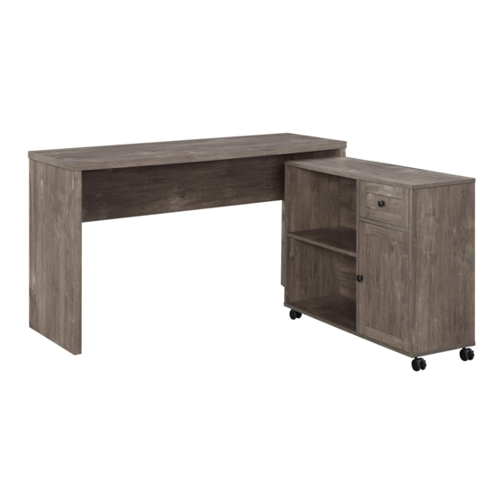
WVY5027
WAVERLY WORK STATION
Assembly Instructions - Important:
Carefully unpack and identify each component before attempting to assemble. Refer to parts list. Please take care when
assembling the unit and always set the parts on a clean, soft surface. If you require any assistance with assembly, parts or
information on other products, please visit our website: www.officestar.net or call or write us.
Advertisement

Related Manuals for OSP Home Furnishings WAVERLY WVY5027


Summary of Contents for OSP Home Furnishings WAVERLY WVY5027
- Page 1 November, 2019 WVY5027 WAVERLY WORK STATION Assembly Instructions - Important: Carefully unpack and identify each component before attempting to assemble. Refer to parts list. Please take care when assembling the unit and always set the parts on a clean, soft surface. If you require any assistance with assembly, parts or information on other products, please visit our website: www.officestar.net or call or write us.
-
Page 2: Limited Warranty
LIMITED WARRANTY OSP Home Furnishings™ warrants to the original purchaser that this product will be free from defects in material and workmanship as described below. OSP Home Furnishings™ will repair or replace, at its option, without charge to the original purchaser only, defective products or parts for one (1) year from the date of purchase. - Page 3 3. Rename all English discriptions to French discriptions. PARTS (A) Desk Top Panel (1 PC) (B) Desk Left Side Panel (1 PC) (C) Desk Right Side Panel (1 PC) (D) Desk Rear Panel (1 PC) (E) Cabinet Top Panel (1 PC) (F) Cabinet Bottom Panel (1 PC) (G) Cabinet Left Side Panel (1 PC) (H) Cabinet Right Side Panel (1 PC)
- Page 4 3. Rename all English discriptions to French discriptions. PARTS (K) Adjustable Shelf (1 PC) (L) Cabinet Right Support (1 PC) (M) Drawer Front Panel (1 PC) (N) Drawer Left Side Panel (1 PC) (O) Drawer Right Side Panel (1 PC) (P) Drawer Back Panel (1 PC) (Q) Drawer Bottom Panel (1 PC) (R) Door (1 PC)
-
Page 5: Hardware List
HARDWARE LIST DRAWING DESCRIPTION SIZE QUANTITY Screw #6.5 x 1/2” 12 PCS + 2 EXTRA White Screw #6.5 x 1/2” 4 PCS + 1 EXTRA Screw #8 x 9/16” 16 PCS + 2 EXTRA Nail Screw 5 PCS + 1 EXTRA Screw #6 x 5/8”... - Page 6 HARDWARE LIST DRAWING DESCRIPTION SIZE QUANTITY Hinge Plate 2 PCS Locking Caster 2 PCS Caster 2 PCS Plastic Spacer 8 PCS + 1 EXTRA Shelf Pin 4 PCS + 1 EXTRA Knob 2 PCS Sticker 5 PCS Phillips screwdriver and hammer also needed for assembly (not provided). CAM LOCK INSTRUCTIONS 180°...
- Page 7 STEP 1 (10) FULLY TIGHTEN ALL CAM SCREWS (10) USING PHILLIPS SCREWDRIVER (NOT PROVIDED). STEP 2 (10) (13) FULLY TIGHTEN ALL CAM SCREWS (10) USING PHILLIPS SCREWDRIVER (NOT PROVIDED).
- Page 8 STEP 3 (13) STEP 4 (12) FULLY TIGHTEN ALL LARGE CAM NUTS (12) USING PHILLIPS SCREWDRIVER (NOT PROVIDED).
- Page 9 STEP 5 (12) FULLY TIGHTEN ALL LARGE CAM NUTS (12) USING PHILLIPS SCREWDRIVER (NOT PROVIDED). STEP 6 (25) (12)
- Page 10 STEP 7 (10) FULLY TIGHTEN ALL CAM SCREWS (10) USING PHILLIPS SCREWDRIVER (NOT PROVIDED). STEP 8 (10) (13) FULLY TIGHTEN ALL CAM SCREWS (10) USING PHILLIPS SCREWDRIVER (NOT PROVIDED).
- Page 11 STEP 9 (10) (13) (19) (15) (15) FULLY TIGHTEN ALL SCREWS (1) AND CAM SCREWS (10) USING PHILLIPS SCREWDRIVER (NOT PROVIDED). STEP 10 (13) (10) (14) (14) FULLY TIGHTEN ALL SCREWS (1) AND CAM SCREWS (10) USING PHILLIPS SCREWDRIVER (NOT PROVIDED).
- Page 12 STEP 11 (12) FULLY TIGHTEN LARGE CAM NUTS (12) USING PHILLIPS SCREWDRIVER (NOT PROVIDED). STEP 12 (12) FULLY TIGHTEN LARGE CAM NUTS (12) USING PHILLIPS SCREWDRIVER (NOT PROVIDED).
- Page 13 STEP 13 (12) FULLY TIGHTEN ALL LARGE CAM NUTS (12) USING PHILLIPS SCREWDRIVER (NOT PROVIDED). STEP 14 (12) FULLY TIGHTEN ALL LARGE CAM NUTS (12) USING PHILLIPS SCREWDRIVER (NOT PROVIDED).
- Page 14 STEP 15 STEP 16 FULLY TIGHTEN ALL SCREWS (6) USING PHILLIPS SCREWDRIVER (NOT PROVIDED).
- Page 15 STEP 17 FULLY TIGHTEN ALL NAIL SCREWS (4) USING HAMMER (NOT PROVIDED). STEP 18 (21) (20) FULLY TIGHTEN ALL SCREWS (3) USING PHILLIPS SCREWDRIVER (NOT PROVIDED).
- Page 16 STEP 19 (22) FULLY TIGHTEN ALL SCREWS (5) USING PHILLIPS SCREWDRIVER (NOT PROVIDED). STEP 20 (23)
- Page 17 STEP 21 (18) (24) FULLY TIGHTEN ALL SCREWS (2 & 8) USING PHILLIPS SCREWDRIVER (NOT PROVIDED). STEP 22 (19) (18) ASSEMBLE HINGE (18) TO HINGE PLATE (19) USING PHILLIPS SCREWDRIVER (NOT PROVIDED).
- Page 18 STEP 23 FULLY TIGHTEN ALL CAM SCREWS (9) USING PHILLIPS SCREWDRIVER (NOT PROVIDED). STEP 24 (11) FULLY TIGHTEN ALL SMALL CAM NUTS (11) USING PHILLIPS SCREWDRIVER (NOT PROVIDED).
- Page 19 STEP 25 STEP 26 FULLY TIGHTEN ALL SCREWS (6) USING PHILLIPS SCREWDRIVER (NOT PROVIDED).
- Page 20 STEP 27 (16) (16) (17) (17) FULLY TIGHTEN ALL SCREWS (1) USING PHILLIPS SCREWDRIVER (NOT PROVIDED). STEP 28 (24) FULLY TIGHTEN SCREW (7) USING PHILLIPS SCREWDRIVER (NOT PROVIDED).
- Page 21 STEP 29 STEP 30 (25)
- Page 22 STEP 31...
Need help?
Do you have a question about the WAVERLY WVY5027 and is the answer not in the manual?
Questions and answers