Sign In
Upload
Manuals
Brands
Texas Instruments Manuals
Motherboard
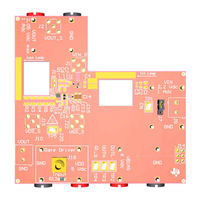
TPS7A14EVM-058
Texas Instruments TPS7A14EVM-058 Board Manuals
Manuals and User Guides for Texas Instruments TPS7A14EVM-058 Board. We have
2
Texas Instruments TPS7A14EVM-058 Board manuals available for free PDF download: User Manual
Texas Instruments TPS7A14EVM-058 User Manual (23 pages)
Brand:
Texas Instruments
| Category:
Motherboard
| Size: 1 MB
Table of Contents
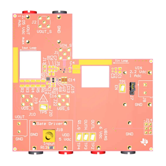
Figure 1-1. TPS7A14EVM-058 Evaluation Module
1
Figure 1-2. TPS7A14EVM-095 Evaluation Module
1
Table of Contents
2
Introduction
3
Setup
3
LDO Input/Output Connector Descriptions
3
Optional Load Transient Input/Output Connector Descriptions
3
TPS7A14 LDO Operation
4
Figure 2-1. TPS7A14EVM-058 Turn on
4
Figure 2-2. TPS7A14EVM-058 with Current Probes Attached
5
Optional Load Transient Circuit Operation
6
Figure 2-3. TPS7A14EVM-058 Load Transient Results: 1-Ma to 950-Ma Load Step
7
Figure 2-4. TPS7A14EVM-058 Load Transient Results: 950-Ma to 1-Ma Load Step
7
Board Layout
8
Figure 3-1. TPS7A14EVM-058 Top Assembly Layer and Silk Screen
8
Figure 3-2. TPS7A14EVM-058 Top Layer Routing
8
Figure 3-3. TPS7A14EVM-058 Layer 2
8
Figure 3-4. TPS7A14EVM-058 Layer 3
8
Figure 3-5. TPS7A14EVM-058 Bottom Layer Routing
9
Figure 3-6. TPS7A14EVM-058 Bottom Assembly Layer and Silk
9
Figure 3-7. TPS7A14EVM-095 Top Assembly Layer and Silk Screen
9
Figure 3-8. TPS7A14EVM-095 Top Layer Routing
9
Figure 3-9. TPS7A14EVM-095 Layer 2
10
Figure 3-10. TPS7A14EVM-095 Layer 3
10
Figure 3-11. TPS7A14EVM-095 Bottom Layer Routing
10
Figure 3-12. TPS7A14EVM-095 Bottom Assembly Layer and Silk
10
TPS7A14EVM Schematic
11
Figure 4-1. TPS7A14EVM-058 Schematic
11
Figure 4-2. TPS7A14EVM-095 Schematic
12
Bill of Materials
13
Revision History
17
Advertisement
Texas Instruments TPS7A14EVM-058 User Manual (17 pages)
Evaluation Module
Brand:
Texas Instruments
| Category:
Motherboard
| Size: 1 MB
Table of Contents
Table of Contents
1
Figure 1-1. TPS7A14EVM-058 Evaluation Module
1
1 Introduction
3
Setup
3
LDO Input/Output Connector Descriptions
3
Optional Load Transient Input/Output Connector Descriptions
3
TPS7A14 LDO Operation
4
Figure 2-1. TPS7A14EVM-058 Turn on
4
Optional Load Transient Circuit Operation
5
Figure 2-2. TPS7A14EVM-058 with Current Probes Attached
5
Figure 2-3. TPS7A14EVM-058 Load Transient Results: 1-Ma to 950-Ma Load Step
6
Figure 2-4. TPS7A14EVM-058 Load Transient Results: 950-Ma to 1-Ma Load Step
6
2 Setup
3
3 Board Layout
7
Figure 3-1. Top Assembly Layer and Silk
7
Figure 3-2. Top Layer Routing
7
Figure 3-3. Layer 2
7
Figure 3-4. Layer 3
7
Figure 3-5. Bottom Layer Routing
8
Figure 3-6. Bottom Assembly Layer and Silk Screen
8
4 TPS7A14EVM Schematic
9
Figure 4-1. Schematic
9
5 Bill of Materials
10
Advertisement
Related Products
Texas Instruments TPS7A13EVM-057
Texas Instruments TPS7A10EVM-004
Texas Instruments TPS7A14EVM
Texas Instruments TPS7A14EVM-095
Texas Instruments TPS7A53EVM-031
Texas Instruments TPS7A54EVM-031
Texas Instruments TPS7A84EVM-753
Texas Instruments TPS7A57EVM-056
Texas Instruments TPS7A94EVM-046
Texas Instruments TPS7A3301EVM-061
Texas Instruments Categories
Motherboard
Control Unit
Microcontrollers
Computer Hardware
Calculator
More Texas Instruments Manuals
Login
Sign In
OR
Sign in with Facebook
Sign in with Google
Upload manual
Upload from disk
Upload from URL