Table of Contents
Advertisement
Quick Links
Operating instructions TruHeat HF Series 1000 / 3000 / 5000
A 05-0099-00.BEN-001-21
Operating instructions
TruHeat HF
Series 1000 / 3000 / 5000
Notice!
This operating manual is required for the safe operation of the device.
Therefore, you should keep the operating manual close to the device.
28.03.2017
Advertisement
Table of Contents

Related Manuals for Trumpf TruHeat HF 1000 Series


Summary of Contents for Trumpf TruHeat HF 1000 Series
- Page 1 Operating instructions TruHeat HF Series 1000 / 3000 / 5000 Notice! This operating manual is required for the safe operation of the device. Therefore, you should keep the operating manual close to the device. Operating instructions TruHeat HF Series 1000 / 3000 / 5000 28.03.2017 A 05-0099-00.BEN-001-21...
- Page 2 This manual is intended for all persons who are working with and on operating instructions the device, and especially for the operating personnel. for? © TRUMPF (TRUMPF Hüttinger GmbH + Co. KG) Manufacturer TRUMPF Hüttinger GmbH + Co. KG Bötzinger Str. 80...
- Page 3 How to reach our Service department: Telephone: +49 761 8971-2170 Fax: +49 761 8971-1178 E-mail: Service.Electronic@de.trumpf.com Operating instructions TruHeat HF Series 1000 / 3000 / 5000 28.03.2017 A 05-0099-00.BEN-001-21...
- Page 4 28.03.2017 Operating instructions TruHeat HF Series 1000 / 3000 / 5000 Item No.: A 05-0099-00.BEN-001-21...
-
Page 5: Table Of Contents
TABLE OF CONTENTS INDEX OF FIGURES ...............9 INDEX OF TABLES ..............11 GENERAL INFORMATION ...........13 WARRANTY ................. 13 STRUCTURE OF THE DOCUMENTATION ........13 ..................13 ENERAL ......... 14 TRUCTURE OF THE OPERATING INSTRUCTIONS ........... 14 TRUCTURE OF THE INDIVIDUAL PAGES ........ - Page 6 VERSIONS, ACCESSORIES ..........43 MODEL VARIATIONS ..............43 ..............43 ECHANICAL VARIANTS ................ 44 LECTRICAL VARIANTS ............... 44 XTERNAL CIRCUIT VARIANTS ........45 XTERNAL VOLTAGE SUPPLY FOR THE CONTROL ACCESSORIES ................47 ........... 47 YROMETER FOR TEMPERATURE REGULATION INSTALLATION ..............49 TRANSPORT, STORAGE ...............
- Page 7 ..........128 TRUCTURE OF COMMUNICATION BLOCK ............130 OMMUNICATION PROCEDURE PROFIBUS .................. 132 ..................132 ENERAL TRUMPF H ........133 ÜTTINGER ROFIBUS COMMANDS Operating instructions TruHeat HF Series 1000 / 3000 / 5000 Chapter : Table of contents Page A 05-0099-00.BEN-001-21...
- Page 8 CANOPEN .................. 137 ................137 BBREVIATIONS ..............137 BUS CONNECTION : ........139 ETTING STATION ADDRESS AND BAUD RATE (RPDO) ..............139 ECEIVE (TPDO) ..............140 RANSMIT (EMCY) ............142 MERGENCY BJECT PROFIBUS AND RS 232 COMMANDS ........143 ........143 ESCRIPTION OF ACKNOWLEDGMENT MESSAGES ........
-
Page 9: Index Of Figures
INDEX OF FIGURES Fig.3.1 Front of desktop device ..............28 Fig.3.2 Rear side of desktop device / 19-inch rack ........29 Fig.3.3 Rear side of module ................. 29 Fig.3.4 Front of external circuit ..............30 Fig.3.5 Rear of external circuit ..............30 Fig.3.6 Conductance - Frequency .............. -
Page 10: Fig.3.1
Fig.6.22 Disable input ..................87 Fig.6.23 Generator setup ................87 Fig.6.24 Generator setup selection ..............87 Fig.6.25 Copying interface configuration ............88 Fig.6.26 Generator setup: Standard interface ..........89 Fig.6.27 Digital inputs DI 0…3 ...............89 Fig.6.28 Digital inputs DI 4…7 ...............89 Fig.6.29 Digital outputs DO 0…3 ..............89 Fig.6.30 Digital outputs DO 4…7 ..............90 Fig.6.31... -
Page 11: Index Of Tables
INDEX OF TABLES Tab.4.1 Pin assignments +0-X1 ..............46 Tab.6.1 Parameters (factory setting) .............. 80 Tab.6.2 Fault messages ................105 Tab.6.3 Warning messages ................. 112 Tab. 8.1 Pin assignment of the AD interface ..........120 Tab. 8.2 Signal assignment of the AD interface ..........122 Tab. - Page 12 Operating instructions TruHeat HF Series 1000 / 3000 / 5000 Chapter : Index of Tables Page A 05-0099-00.BEN-001-21...
-
Page 13: General Information
The duration of the warranty is specified in the order confirmation and in the general terms and conditions of sale and delivery of TRUMPF Hüttinger GmbH + Co. KG . Damage caused by improper use or unauthorized modification of the device does not constitute grounds for a warranty claim. -
Page 14: Structure Of The Operating Instructions
TRUCTURE OF THE OPERATING INSTRUCTIONS These operating instructions consist of a total of eight chapters that contain the information necessary for operating the system: • Chapter 1: "GENERAL INFORMATION" • Chapter 2: "SAFETY" • Chapter 3: "DESCRIPTION, TECHNOLOGY" • Chapter 4: "VARIANTS, ACCESSORIES" •... - Page 15 Danger: High frequency! This sign warns of dangers from high-frequency radiation. Persons with pacemakers or implants must keep out of areas labeled with this sign, as the function of a pacemaker can be disturbed or an implant can be heated by the high-frequency radiation. Symbol for protective earth This sign indicates that the generator requires a PE protective earth connection for safety.
-
Page 16: Technical Terms And Abbreviations
TECHNICAL TERMS AND ABBREVIATIONS ESCRIPTION OF THE ABBREVIATIONS Actual value Nominal value Set value RF output current Inverter Output voltage of inverter (of power supply unit) Capacitor voltage Intermediate circuit voltage Current in intermediate circuit of inverter bridge 1 Current in intermediate circuit of inverter bridge 2 Power in the intermediate circuit ESCRIPTION OF THE TECHNICAL TERMS Interlock... -
Page 17: Safety
SAFETY Who is this chapter This chapter is intended for all persons who install, operate, and main- directed at? tain TruHeat HF Series 1000 / 3000 / 5000 Generators on the basis of this operating manual. Content The chapter contains the principal details for the safe operation of the product. -
Page 18: Ntended Use
NTENDED USE Inductive heating The RF generator is designed as a stationary energy source for induc- tive heating. NAUTHORIZED OPERATING METHODS The RF generator may only be used within the scope of its intended use. Unauthorized use refers particularly to •... -
Page 19: General Warning Notices
GENERAL WARNING NOTICES ANGERS FROM HIGH VOLTAGES Life threatening voltage! The high voltages that occur in the generator and at the inductor are absolutely life threatening! In order to generate the electromagnetic fields necessary for induction, the generator produces voltages that could jeopardize human life or health. -
Page 20: Danger From Electromagnetic Fields
ANGER FROM ELECTROMAGNETIC FIELDS Danger: Electromagnetic fields! Strong electromagnetic fields arise in the area near the inductor coil. Electromagnetic fields can have a damaging effect on active and pas- sive health aids (pacemakers, implants, …). The inductor generates an electromagnetic field. Through induction, this induces eddy currents in a metal work piece which is, as a result, heated. - Page 21 What you as the user must observe: Make certain that only trained personnel have access to the in- duction system. Prevent persons with pacemakers and / or implants (e.g. artificial joints) from accessing the induction system. At all entrances to the room in which the device is operated, af- fix the supplied adhesive signs "No Pacemakers".
-
Page 22: Dangers From High Temperatures
ANGERS FROM HIGH TEMPERATURES Risk of injury from heated components! The use of induction on metal work pieces always results in heating. During induction, extremely high temperatures can be attained on the work piece unexpectedly fast (in seconds). Particularly dangerous is the temperature range below the annealing temperature, because this is not visually recognizable. -
Page 23: Dangers During Maintenance And Repair
DANGERS DURING MAINTENANCE AND RE- PAIR During certain service work, field strengths greater than those in nor- mal operation may occur. In the event of a malfunction, high-frequen- cy fields with amplitudes greater than the limit values specified by EN 55011 can likewise not be excluded. ANGERS WITH SWITCHED OFF DEVICE SWITCH Even with the device switch switched off, the following parts still carry... -
Page 24: Safety Devices
SAFETY DEVICES ONITORING AND PROTECTION DEVICES Notice! You, as the operator, are responsible for the safe operation of the RF generator. It is your responsibility to become familiarized with the ap- plicable legal regulations and to apply them. Personal safety For induction applications the coil must be protected from physical contact, as dangerous RF voltage is present during generator opera- tion. -
Page 25: Emergency Measures
EMERGENCY MEASURES In an emergency, carry out the following steps in the given or- der: Switch off the external mains separation device for the RF generator. Turn off the cooling water supply for the generator. Put out any fires with a suitable extinguisher. Life threatening voltage! Due to present mains voltages, never extinguish the fire with water but instead with appropriate extinguishing agents. - Page 26 Operating instructions TruHeat HF Series 1000 / 3000 / 5000 Chapter 2: Safety Page A 05-0099-00.BEN-001-21...
-
Page 27: Description, Technology
DESCRIPTION, TECHNOLOGY Who is this chapter This chapter is intended for all persons who install, operate, and main- directed at? tain TruHeat HF Series 1000 / 3000 / 5000 Generators on the basis of this operating manual. Content The chapter contains information about the functionality and technol- ogy of the TruHeat HF Series 1000 / 3000 / 5000 Generators, their use, fields of application, and technical data. -
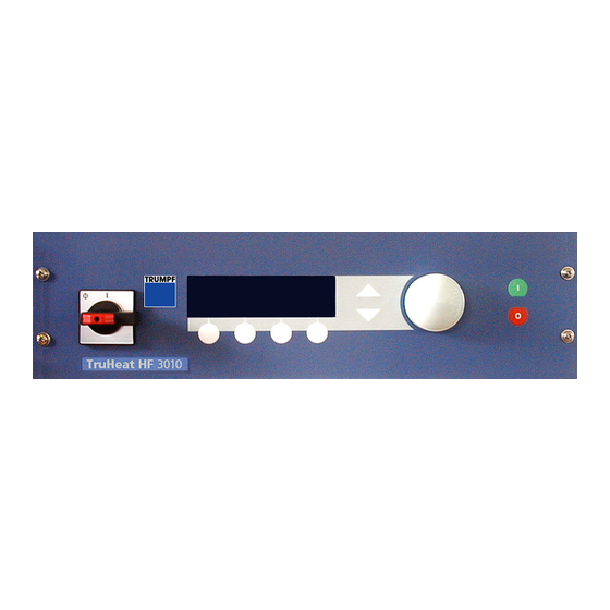
Page 28: Operating Elements And Connections
All variants of the generator are water-cooled and housed in an alumi- num casing. For operation, the power supply is connected to the ex- ternal circuit, using the power cable intended for this purpose, and two control cables. The external circuit is also a water-cooled device housed inside an alu- minum case. -
Page 29: Rear Side Of Desktop Device / 19-Inch Rack
Rear side of desktop Cables for power device / Bushings for interface Cooling water supply and out- 19-inch rack cables connections Bolt for potential equalization Fig.3.2 Rear side of desktop device / 19-inch rack The interface connections and the three status LEDs on the desktop device are only accessible after a cover is removed. -
Page 30: Front Of External Circuit
Front of external circuit Inductor jaws with integrated cool- ing water duct for connecting the inductor Fig.3.4 Front of external circuit Rear of external circuit Bolt for protective earth Connections to the power supply unit RF power input Cooling water Cooling water connection of in- connection of... -
Page 31: Technology
TECHNOLOGY TruHeat HF Series 1000 / 3000 / 5000 Generators are fully transistor- ized and µC-controlled RF generators that recommend themselves for their compact size, low weight, robustness, reliability and easy mainte- nance. The protection against mismatches, overload, and short circuit at the load, which is particularly important in induction technology applica- tions, is given by overdimensioning in conjunction with electronic monitoring functions. -
Page 32: Control Modes
Basic matching of the load is achieved, irrespective of the resonance frequency, by means of external circuits with different transformer transformation ratios. Here, however, rated power is also achieved for each individual external circuit across a broad load range (see external circuit specifications). -
Page 33: Operation And Matching
By configuring "User Settings" it is also possible to make certain com- mands and signals available via the AD interface, even if an interface other than the AD interface is preselected. For example, it is therefore possible to set the Profibus interface as the active interface; the "Pow- er ON"... -
Page 34: Load Matching
Scaled conductance Normalized frequency Fig.3.6 Conductance - Frequency The Y-axis shows the conductance of the oscillator circuit. It is scaled, i.e. conductance has the value 1 at the resonance frequency. The cir- cuit frequency relative to the resonance frequency is plotted on the X- axis, i.e. -
Page 35: Equivalent Circuit Diagram Showing External Circuit And Load
Trans- Inductor jaws ü Fig.3.7 Equivalent circuit diagram showing external circuit and load For reasons of symmetry, the capacitors (Cx) are distributed along the forward and return line in the external circuit. The load consists of the serially connected inductive components (L) of the inductor and work piece, and their ohmic components (R). -
Page 36: Load Matching
RF current regulator Power regulator Limit frequency regulator I RF Current prox. load Ideal matching Fig.3.8 Load matching The diagram is only valid if all set values are at their maximum value; this ensures that no regulator can restrict the output variables owing to a small set value. -
Page 37: Frequency Matching
Note: This value will only provide accurate information if all set values are set at their maximum value. A characteristic feature of TruHeat HF Series 1000 / 3000 / 5000 Gen- erators is that load matching can be performed independently of fre- quency matching (dealt with in the next section). - Page 38 tion is not monitored by the power supply unit itself; an appropriate error message is output in the case of operation in non-permissible ranges. The second restriction depends on compliance with the permissible op- erating parameters of the used capacitors in the series oscillator circuit. Since capacitors with various rated values are available for installation, and additionally the circuit is a series and parallel circuit (see Fig.3.10 on page 39), currents and voltages could occur (depending on the ca-...
-
Page 39: Starting Procedure
Transformer Fig.3.10 Capacitor voltage in external circuit Warning! The capacitor voltage can only be correctly measured and monitored if the settings for the capacitor configuration and for the transformer are correct. If the configuration is changed, the operator is responsible for making sure that these parameters are set correctly. - Page 40 Note: The changed "FSTART" value is not stored in the menu until it is confirmed with "OK". If the start frequency is too far above the resonance frequency of the load circuit, a very small and therefore non-measurable RF current is produced during the start procedure which results in an error message ("Commutation Error"...
-
Page 41: Fields Of Application
FIELDS OF APPLICATION The generator is designed to supply high-frequency energy for the in- ductive heating of conductive and semiconductive materials. Typical fields of application are for example: • Hardening • Soldering (hard soldering and soft soldering) • Welding • Forging •... - Page 42 Operating instructions TruHeat HF Series 1000 / 3000 / 5000 Chapter 3: Description, Technology Page A 05-0099-00.BEN-001-21...
-
Page 43: Versions, Accessories
VERSIONS, ACCESSORIES Who is this chapter This chapter is intended for all persons who install and operate special directed at? variants of the basic model of the TruHeat HF Series 1000 / 3000 / 5000 Generators or accessories for them. Content The chapter contains information about the functionality and technol- ogy of model variants and accessories of the TruHeat HF... -
Page 44: Electrical Variants
LECTRICAL VARIANTS • Output powers 10 kW • Supply voltages 3 x 400 V - 3 x 200 / 208 V (only for 5 kW output power) The electrical variants differ from each other only in the dimensions of their power components. All other functions, construction and opera- tion are identical. -
Page 45: External Voltage Supply For The Control
XTERNAL VOLTAGE SUPPLY FOR THE CONTROL The generator control can be supplied by an external voltage source. If the main circuit is interrupted, the control remains active and the gen- erator is ready for use immediately after it is switched on again. The external supply must be designed by the customer. -
Page 46: Fig.4.2
Cable -W11.1 Fig.4.2 Connection cable for the external voltage source Pin assignments Assignment +0-X1: Tab.4.1 Pin assignments +0-X1 Operating instructions TruHeat HF Series 1000 / 3000 / 5000 Chapter 4: Versions, accessories Page A 05-0099-00.BEN-001-21... -
Page 47: Accessories
In combination with a pyrometer and a temperature regulator from the Sensortherm company, the power delivery of the generator can be regulated as a function of temperature. Please contact TRUMPF to obtain more detailed information on the ac- cessories. Operating instructions TruHeat HF Series 1000 / 3000 / 5000... - Page 48 Operating instructions TruHeat HF Series 1000 / 3000 / 5000 Chapter 4: Versions, accessories Page A 05-0099-00.BEN-001-21...
-
Page 49: Installation
In order to retain the right of recourse, report any damages in- curred during transport immediately in writing to the forward- ing agency, the insurance company and TRUMPF. Operating instructions TruHeat HF Series 1000 / 3000 / 5000 Chapter 5: Installation Page A 05-0099-00.BEN-001-21... -
Page 50: Position
OSITION Warning! TruHeat HF Series 1000 / 3000 / 5000 Generators and external circuits must only be transported and stored in the position shown in fig. 5.1. If transported or stored in a different position, the power components could come out of their holders and cause electrical damage. Fig.5.1 Position for transport, storage and installation TORAGE CONDITIONS... -
Page 51: Unpacking
UNPACKING Carefully unpack the generator. Remove the plastic cover. ACKAGING MATERIAL Disposal If the packaging will not be kept for possible transport at a later time, it should be disposed of properly. The following materials are used for packaging and for the protection of the equipment: •... -
Page 52: Installation And Assembly
INSTALLATION AND ASSEMBLY Note installation position! Both the power supply as well as the external circuit may only be op- erated in horizontal position (see Fig.5.1 on page 50). If installed in any other position, the power components could become unfastened from their holding devices and cause electrical damage. - Page 53 Warning! The ambient temperature must not be higher than that given in the document "Technical Specifications". When installing several generators in one switching cabinet: Ensure (if necessary through additional ventilation measures) that each generator has an unobstructed air flow with a maxi- mum incoming air temperature corresponding to that stated in the Technical Specifications.
-
Page 54: Connecting
CONNECTING AFETY Life threatening voltage! RF generators are connected to the voltage specified on the rating plate! Qualified personnel The electrical connection of the RF generators must only be carried out by personnel who are qualified and trained for work with electrical equipment. -
Page 55: Connecting The Inductor
ONNECTING THE INDUCTOR Voltages at inductor! Voltages are present at the inductor while switching is switched on (even with setpoint specification "0"): The operator must attach suitable covers and safety equipment as touch protection. Four threads are provided on the inductor connec- tion for fastening the cover (Fig.5.3). -
Page 56: Connecting The Cooling Water Supply
ONNECTING THE COOLING WATER SUPPLY Power supply unit Connect the cooling water lines to the power supply unit accord- ing to Fig. 5.4. Avoid confusion of inflow and outflow. Outflow Inflow Fig.5.4 Cooling water connections on the power supply unit ... -
Page 57: Cooling Water Supply For Desktop Device And 19- Inch Rack
OOLING WATER SUPPLY FOR DESKTOP DEVICE AND INCH RACK Inflow with Water distribution (1...4) filter Outflow Fig.5.6 Water distribution in desktop device / 19-inch rack At the rear of the desktop device and 19-inch rack there is a water dis- tribution module (Fig. -
Page 58: Connecting The Safety And Control Circuits
The user interfaces are located at the rear side of the device. Interfaces X1501 Fig.5.7 User interfaces • X8 AD interface (with interlock) • X7 TRUMPF Hüttinger bus • X6 RS 232 - Service • X4 RS 232 • X10 Profibus • X11 CAN bus • X1501 Voltage measurement... -
Page 59: Safety And Control Circuits In Desktop Device And 19- Inch Rack
AFETY AND CONTROL CIRCUITS IN DESKTOP DEVICE INCH RACK Fig.5.8 Entry for interface cables On the desktop and 19-inch rack variants, the interface connections can only be accessed after the strain relief has been unscrewed and re- moved (Fig. 5.8). The strain relief can be opened to allow the lines to be fed through. -
Page 60: Establishing The Connections Between The Power Supply Unit And The External Circuit
Power ca- Fig.5.10 Connections, power supply unit - external circuit The lines for the TRUMPF Hüttinger bus and voltage measurement are protected against polarity reversal. The power cable is already attached to the external circuit and only has to be connected to the power supply unit. - Page 61 The power cable is preattached in the way shown in Fig. 5.11 and Fig. 5.12. Threaded bolt Preattached pow- er cable Fig.5.12 Power output Screw the wires of the power cable to the threaded bolts (Fig. 5.12). Operating instructions TruHeat HF Series 1000 / 3000 / 5000 Chapter 5: Installation Page A 05-0099-00.BEN-001-21...
-
Page 62: Connections Between Power Supply Unit And External Circuit
ONNECTIONS BETWEEN POWER SUPPLY UNIT AND EX TERNAL CIRCUIT ON DESKTOP DEVICE AND INCH RACK In this device variant, the power cable is already connected to the ex- ternal circuit and the power supply unit. If the external circuit is to be exchanged, the connection must be detached on one side. -
Page 63: Connecting The Mains Supply
ONNECTING THE MAINS SUPPLY Emergency-power-off If an emergency-power-off switch is connected, it is to be in- stalled so that when activated it triggers the external mains sep- switch aration device of the RF generator. Life threatening voltage! Before connecting the mains cable, make certain that the external mains separation device is open and is protected against switching on again. -
Page 64: Onnecting Power Supply For Desktop Device And Inch Rack
ferrite core 3 lines of mains voltage Fig.5.16 Ferrite core Checking After all electrical connections have been made, electrical connections Check that all plugs and cables are fitted securely. Closing the Put all the covers that you have previously removed back on and close power supply unit and external circuit. -
Page 65: Connecting The Potential Equalization On External Circuit
ONNECTING THE POTENTIAL EQUALIZATION ON EXTER NAL CIRCUIT Warning! The external circuit requires potential equalization for safe operation. A threaded bolt is provided on the rear side of the external circuit for this purpose (Fig.5.17). Connect an equipotential bonding conductor to the threaded bolt of the power supply. -
Page 66: Connecting The Potential Equalization On Power Supply
Pyrometer from the Sensortherm company "Regulus RD.." temperature regulator from the Sensortherm company Preassembled connection cable incl. foot switch (mat. no. 1811341) Use only accessory parts supplied by TRUMPF. Connect the connection cable with the foot switch between gen- erator and temperature regulator (Fig. -
Page 67: Fig.5.19
Generator Regulator Foot switch Fig.5.19 Temperature regulator connection Genera- Regulator Foot switch Fig.5.20 Pin assignment of cable 1811341 Operating instructions TruHeat HF Series 1000 / 3000 / 5000 Chapter 5: Installation Page A 05-0099-00.BEN-001-21... -
Page 68: Matching
MATCHING The capacitor configuration in the external circuit can be changed in order to match the frequency. Refer to the detailed description in chapter 3.5: "Operation and matching". Capacitors C1…C4 Fig.5.21 Open external circuit Operating instructions TruHeat HF Series 1000 / 3000 / 5000 Chapter 5: Installation Page A 05-0099-00.BEN-001-21... -
Page 69: Dismantling, Packing
DISMANTLING, PACKING NSURING VOLTAGE FREE COMPONENTS Switch off the generator (information on this can be found in chapter 6: "Operation, Control"). Open the mains separation device in the external electrical unit. Remove all covers to the generator that lie before the electrical connections. - Page 70 • Metals Aluminum Copper Steel Brass Sheet iron Galvanized sheet steel • Plastics Teflon Epoxy PA and others • Other Cardboard Ceramics Semiconductors Operating instructions TruHeat HF Series 1000 / 3000 / 5000 Chapter 5: Installation Page A 05-0099-00.BEN-001-21...
-
Page 71: Operation, Control
OPERATION, CONTROL Who is this chapter This chapter is intended for all persons who operate TruHeat HF directed at? Series 1000 / 3000 / 5000 Generators on the basis of this operating manual. Content The chapter contains a description of the modes and states of opera- tion as well as operating instructions for TruHeat HF Series 1000 / 3000 / 5000 Generators. -
Page 72: Operation Via Control Module
OPERATION VIA CONTROL MODULE Notice! The terminal program "Tera Term" is used for operation in the case of the generator variant without control module. The display of the con- trol module is reproduced on the PC (see "Operation via RS 232 service interface”... -
Page 73: Display Elements On Rear Side
ISPLAY ELEMENTS ON REAR SIDE LED mains OK (green) LED Power ON (yellow) LED aggregated fault (red) Fig.6.2 LEDs rear side ONTROL SYSTEM Buttons for power The power operation is switched on by pressing the green ON button ON/OFF (I). By pressing the red OFF button (O), the power operation is switched off. -
Page 74: Recognition Of Operational States
Function keys The function keys are used to move between and within the menus, as well as to select parameters. The functions assigned to the function keys vary from menu to menu. They are indicated in the display, which is located directly above the function buttons. For more information please refer to the individual menu descriptions. - Page 75 Power output Password protection active Ramp function or process control active Timer active Operating instructions TruHeat HF Series 1000 / 3000 / 5000 Chapter 6: Operation, Control Page A 05-0099-00.BEN-001-21...
-
Page 76: Menu Structure
MENU STRUCTURE page 79 Main menu Start menu page 77 (Selection) Check external page 77 circuit External circuit Find FSTART page 77 page 78 Operating param- Protected mode Generator setup Diagnosis Service Set / actual value eters display page 79 page 80 page 86 page 87... -
Page 77: Start Menu
START MENU Continue Fig.6.5 Start menu After connecting the supply voltage, the display briefly shows the com- pany logo and then the "Check external circuit" menu. If the generator is operated with the terminal program via the RS 232 service interface, the "Set / actual value display" menu appears imme- diately. - Page 78 Start menu > Automatic search FSTART Check external circuit > Ready Automatic search Warning: Process results in FSTART voltage at the inductor! FSTART XX kHz Start Fig.6.8 Start - Automatic search FSTART Warning While determining the start frequency, voltage is present at the induc- tor.
-
Page 79: Main Menu
MAIN MENU Main menu Set / actual value display Operating parameters Protected mode Generator setup Diagnosis Service Enter Fig.6.10 Main menu The Main Menu is used as a selection menu; you can select an entry using the up/down buttons or the handwheel (the symbol indicates the selected entry). -
Page 80: Operating Parameters
Changing set values: To change a set value you must first select the variable to be changed using the up/down buttons or the handwheel. The selected variable is indicated by the symbol (e.g. in fig. 6.11). The editing mode can Edit then be selected with (indicated by the flashing cursor under a... -
Page 81: Selecting And Copying A Parameter Set
Parameters Ramp function Status Channel Start value Ramp time 0.00s Process control Status I start value 2.8A P start value 0.00kW UC start 200V value Set / actual value devia- 0% after 0s tion 0% after 0s 0% after 0s 0% after 0s Tab.6.1 Parameters (factory setting) -
Page 82: Onfiguring Parameters
operating parameter set is copied into the operating parameter set that is selected in Copy to operating parameters by using the Copy function key Configure To change an operating parameter set, it must be selected first. It can Configure then be called via . -
Page 83: Imer Submenu
IMER SUBMENU Main menu > Timer P 3/7 Operating parameters > Status Configure parameter Off time set > msec Timer Back Cursor Edit Fig.6.15 Timer If the timer is active ( status ON ), the set time and the timer symbol ) are shown in the Set/actual value display menu. -
Page 84: Process Control Submenu
ROCESS CONTROL SUBMENU Main menu > Process control P 3/7 Operating parameters > Status 8 Steps active Configure parameter I start value 0.0A set > P start value : 0.00kW Process control UC start value : Back Cursor Edit Fig.6.17 Process control Activation of process control ( status: Step active... -
Page 85: Fig.6.19
Example of process control with 3 steps Step 1 Step 2 Step 3 Final val- ue of Step Start value (RP=0) RT = Ramp time RP = Running period Fig.6.18 Process control diagram To set the values for the individual steps, you must scroll down the Pro- cess Control menu with the asterisk ( ). -
Page 86: Set Actual Value Deviation Submenu
ACTUAL VALUE DEVIATION SUBMENU Main menu > Set / actual value deviation monitoring P 0/7 Operating parameters > 0.0 % after > > 0.0 % after Configure parameter > 0.0 % after set > C3 : > after Set / actual value deviation Back Cursor... -
Page 87: Generator Setup
Protected mode Block parameter entry Protect setpoint specifications Cancel Edit Fig.6.22 Disable input With this menu option, all process-relevant generator parameters can be protected. Block parameter If this option is active, you must enter the password when you call up entry the operating parameters. -
Page 88: Nterfaces
The submenu is selected here. NTERFACES Main menu > Configuration Panel Generator setup > copy to User 1 Interfaces Profibus address RS 485 bus address CANopen node ID CANopen baud rate 125kBaud Copy Configure Edit Fig.6.25 Copying interface configuration Configuration Indicates which interface is used to operate the generator. - Page 89 User 1 Enter the standard interface (serial connection to Host-PC or system control) : Terminal Cancel Forward Edit Fig.6.26 Generator setup: Standard interface Forward First, you select the standard interface. Using you can then call up the inputs and outputs of the AD interface in sequence. Digital inputs of the Digital inputs A/D User 1...
-
Page 90: Tab.6.3
Digital Outputs A/D User 1 Port Descr. Polarity DISABLE HIGH DISABLE HIGH DISABLE HIGH DISABLE HIGH Back Forward Enter Fig.6.30 Digital outputs DO 4…7 Port DO0 … DO7 Number of the digital outputs Descr. Signals which can be assigned to the digital outputs ( DISABLE = no signal assigned). -
Page 91: External Circuit
Analog outputs of AD Analog Outputs A/D User 1 interface Port Descr. min - DISABLE DISABLE DISABLE DISABLE Back Forward Enter Fig.6.32 Analog outputs AO 0…3 Port AO0 … AO3 Number of the analog outputs Descr. Signals which can be assigned to the analog outputs ( DISABLE = no signal assigned). -
Page 92: Power Supply Unit
UC regulator Enables regulation of the capacitor voltage. If the capacitor and trans- former settings are correct, the capacitors are protected with respect to their permitted operating values by restricting the set values for cur- rent and voltage. If a restriction occurs owing to the capacitor protec- tion settings, this is indicated in the display by flashing of the respective set value. -
Page 93: Ontrol Panel
ONTROL PANEL Main menu > Menu language English Generator setup > Display contrast Control panel Dimming Inverse display Beep Percentage display Cancel Cursor Edit Fig.6.35 Control panel Percentage display not yet possible HANGE PASSWORD Main menu > Generator setup > Change password old: 0 3 5 0... -
Page 94: Automatic Search Fstart
Factory settings The device settings that existed when the device was delivered are re- stored. FSTART UTOMATIC SEARCH Main Menu > Automatic search FSTART Generator Setup > Automatic Search Ready FSTART Warning: Process results in voltage at the inductor! FSTART XX kHz Back Start... -
Page 95: Diagnosis
6.11 DIAGNOSIS No changes can be made in the diagnosis menus. Main menu > Measurement display Diagnosis > Current warnings Current faults Error log Version data HW / SW Back Enter Fig.6.39 Diagnosis Selection menu EASUREMENT DISPLAY Main menu > Cooling Diagnosis >... -
Page 96: Tab.4.1
Main menu > Memorize 64512 IILK I_SET 32798 Diagnosis > IFEHL ODDS U_SET 32810 Measurement display OFEHL 1 OIMIN T_IST 32768 > IRES IT/F T_REG 33624 Inverter unit ORES OFQCP 1 F_REG 8592 IPOW IT/TZ I_REG 8622 OPOW U_REG 8622 Back Fig.6.42 Measurement display ->... -
Page 97: Arning Messages
ARNING MESSAGES Main menu > Warning messages Diagnosis > Warning messages < 30009 > Invalid interface <32332> Water flow at transformer too low Reset Next Prev. Fig.6.45 Warning messages Pending warning messages can be deleted with the "Reset" function key, provided that they are no longer current. Warning messages do not cause the generator to be switched off. -
Page 98: Perating Time Counter
The 20 most recent errors are displayed together with a time stamp (sequence in which the errors occurred). The most recent error is 0/19 the next error is , and so on. 1/19 PERATING TIME COUNTER Main menu > Mains on 0.823 ksec Diagnosis >... -
Page 99: Service
Cancel Cursor Edit Fig.6.50 Service menu The service area is reserved for TRUMPF service personnel and can thus only be entered with a password. Operating instructions TruHeat HF Series 1000 / 3000 / 5000 Chapter 6: Operation, Control Page A 05-0099-00.BEN-001-21... -
Page 100: Operation Via Rs 232 Service Interface
6.13 OPERATION VIA RS 232 SERVICE INTERFACE The generator (with versions without an operator module) can also be operated using the terminal program "Tera Term" which is supplied with the generator. To allow this, the serial interface of the PC must be connected to the RS 232 Service (X6) interface of the generator. -
Page 101: Operation Via Trucontrol Power Software
6.14 OPERATION VIA TRUCONTROL POWER SOFT- WARE The TruControl Power software permits easy operation of the gener- ators. Requirement Computer on which the TruControl Power software is installed. Auxiliary equipment, • Shielded null-modem cable (see Fig.8.6 on page 127). tools, material ... -
Page 102: Operation With Pyrometer
AD interface of the generator. These signals are used to regulate the power delivery of the generator as a function of temper- ature. Regulation can be activated with the foot switch (see fig. 6.53). Use only accessory parts supplied by TRUMPF: Pyrometer "Regulus" temperature regulator Connection cable incl. -
Page 103: Configuration On The Temperature Regulator
ONFIGURATION ON THE TEMPERATURE REGULATOR Use the Regulus II Win software to set the regulator. The software is included in the scope of delivery of the regulator. Select the settings according to fig. 6.54. Start / Stop controller Aktivate controller Fig.6.54 Configuration with Regulus II Win... -
Page 104: Troubleshooting, Rectification Of Faults
6.16 TROUBLESHOOTING, RECTIFICATION OF FAULTS AULT AND WARNING MESSAGES Depending on the severity and type of the fault, they are classified into those which lead to the immediate shutdown of the generator and those which do not impede the operation. Accordingly, a fault or warning message is created in the case of a fault. - Page 105 Fault Fault descr. Fault cause 18001 RAM error Internal system error, RAM defective 18002 Checksum Internal system error, ROM defective FLASH 18003 CPLD error Software status in CPLD is not identical to software status which is stored in controller; CPLD program has been changed, or hardware is faulty. 18004 DSP error Problem affecting communication with DSP (control unit)
- Page 106 Fault Fault descr. Fault cause 18017 CANopen PDO The length of a receive PDO was too short. length < 18100 Overvolt. Overvoltage in direct voltage intermediate circuit (higher than approx. interm. circ. 800V). Mains voltage too high or unacceptably high hum in intermediate LEM module circuit voltage, e.g.
-
Page 107: Tab.6.2
Fault Fault descr. Fault cause 18107 Overcurr. IRF, RF overcurrent at power supply unit output during positive current half- pos. half-wave wave. Error is triggered at an effective value of approx. 50A, irrespective of the device variant. The error occurs if a short-circuit occurs outside the power supply unit. - Page 108 Fault Fault descr. Fault cause 18115 Overcurr. IDrain, "Short-circuit at transistor with designation "ao" in inverter bridge 1. There ao bridge 1 are several reasons why this error message is output: 1. There may be a short-circuit at the output outside the power supply unit; in this case it is usually the error messages 18106 and/or 18107 that occur.
- Page 109 Fault Fault descr. Fault cause 18133 Excess temp. at Temperature on the inverter PCB is greater than or equal to 68°C inverter unit 18134 Excess temp. at Temperature at cooling plate 1 is greater than or equal to 60°C cooling plate Possible causes for this error message are, for example: No or not enough cooling water Clogged filter in water distribution block of 19"...
- Page 110 Interlock open The interlock circuit is not closed. The circuit is looped through plug X7 (TRUMPF Hüttinger bus) and X8 (AD interface). The loop has a break. A detailed description of the interlock is given in chapter 8: "Interfaces". 18149 Group error Logic OR operation of all errors which are detected by the control unit.
- Page 111 Fault Fault descr. Fault cause 20297 UD < limit Intermediate circuit voltage is not suitable for the set mains voltage (too low). The device is possibly connected to a mains voltage which is not per- mitted for this device. 20314 Water flow at The cooling water flow of the transformer circuit in the external circuit is transformer <...
-
Page 112: Warning Messages
ARNING MESSAGES Warn- Warning Cause name 30001 Waiting time not The wait time between data storage operations to the EEPROM has not elapsed been observed; no further storage operations are therefore performed. 30002 Waiting time not The wait time between data storage operations to the EEPROM has not elapsed been observed;... - Page 113 Warn- Warning Cause name 31050 Energy limit Not used value exceeded 31297 UD > limit Unacceptable mains voltage. The intermediate circuit voltage and, there- fore, the mains voltage are too high. 31314 Water flow at The flow volume in the transformer cooling circuit is too high. transformer >...
- Page 114 Operating instructions TruHeat HF Series 1000 / 3000 / 5000 Chapter 6: Operation, Control Page A 05-0099-00.BEN-001-21...
-
Page 115: Maintenance
Screw fitting Sealing ring Fig.7.1 Screen and sealing ring Further maintenance work should only be carried out by TRUMPF ser- vice personnel and specially trained technicians. ECHNICAL SUPPORT The TRUMPF service staff can be contacted via the TRUMPF headquar- ters. - Page 116 Operating instructions TruHeat HF Series 1000 / 3000 / 5000 Chapter 7: Maintenance Page A 05-0099-00.BEN-001-21...
-
Page 117: Interfaces
INTERFACES Who is this chapter This chapter is intended for all persons who operate TruHeat HF directed at? Series 1000 / 3000 / 5000 Generators on the basis of this operating manual. Content This chapter contains detail information about the interfaces of the TruHeat HF Series 1000 / 3000 / 5000 Generators. -
Page 118: Analog-Digital Interface
ANALOG-DIGITAL INTERFACE This interface can be used to control the basic functions of the gener- ator remotely. AD interface AD interface X8 Fig.8.1 AD interface The AD interface is a 37-pin Sub-D socket with screw-type locking. On delivery, the interface has a plug which bridges pin 2 and 21 (inter- lock). -
Page 119: Fig.6.2
AD interface, basic circuit +24 V Interlock 8 x D_OUT 10 x D_IN D_IN_CPLD D_IN_BOOT GND 24V GND ANALOG 4 x A_OUT – AI0+ AI0- AI1+ AI1- – AI2+ AI2- 3 x A_IN Fig.8.2 AD interface, basic circuit Warning! The plugs and cables connected to this interface must be shielded. Connect the shielding to the connector housing. -
Page 120: Fig.6.5
Descr. Meaning Electrical data +24V2 24V control voltage =500mA GND_24V2 Ground to control voltage 24V, ground of digital inputs and outputs ILK_OUT Interlock output U=24V =20mA ILK_IN Interlock input Digital outputs Low –> 0V High –> 18…24V =10mA Minimum load resis- tance: 2.7k*Ω... -
Page 121: Signal Assignment
Descr. Meaning Electrical data AI0+ Analog input No. 0 0-10V ≈100k*Ω AI0- AI1+ Analog input No. 1 AI1- AI2+ Analog input No. 2 AI2- Description of the signal: see Tab. 8.4 on page 123 to Tab. 8.6 on page 125 Tab. -
Page 122: Tab. 8.3 Tab
Pin / Level Panel RS-232 Profi- CANo- Termi- REGU- User 1 User 2 descrip- inter- tion face (TEMP) HIGH DISABLE DISABLE DISABLE DISABLE DISABLE POWER ON DISABLE HIGH DISABLE DISABLE DISABLE DISABLE DISABLE RESET DISABLE HIGH DISABLE DISABLE DISABLE DISABLE DISABLE DISABLE DISABLE... -
Page 123: Signals For Digital Inputs
IGNALS FOR DIGITAL INPUTS Signal Meaning POWER ON Command for switching power delivery on and off, level-controlled. KEYING "Power ON" command (keying). If this signal is assigned to a digital input, an AND oper- ation comprising POWER ON and KEYING is produced. The "Power ON" command is then only executed if POWER ON and KEYING are active. -
Page 124: Tab. 8.9 Tab
Error message One of the measured temperatures is lower than 1°C INTERLOCK Error message The interlock circuit (via regulator PCB, TRUMPF Hüttinger bus and AD interface) is not closed USER Error message Error message relating to user interlock No. 1 to which a digital input... -
Page 125: Ignals For Analog Inputs
IGNALS FOR ANALOG INPUTS Signal Meaning NV_CURRENT Set value of the RF output current (IHF) NV_POWER Set value of the power NV_VOLTAGE Set value of the voltage at the series circuit capacitors NV_OPTIONAL Set value of an optional variable (this variable is regulated by an internal software reg- ulator;... -
Page 126: Rs 232 Service
RS 232 SERVICE Fig.8.3 RS 232 service interface The RS 232 Service interface is a 9-pin Sub-D plug with screw-type locking. The RS 232 service interface is used to operate the generator via the terminal program "ttermpro.exe" supplied. To allow this, the serial in- terface of the PC must be connected to the RS 232 Service interface of the generator. - Page 127 RS 232 Fig.8.5 RS 232 interface The RS 232 interface is a 9-pin Sub-D plug with screw-type locking. This interface is suitable for generator control. Unlike the "RS 232 Ser- vice" interface, this interface offers a specific protocol that includes the check sum monitoring.
-
Page 128: Structure Of Communication Block
TRUCTURE OF COMMUNICATION BLOCK The RS 232 interface protocol implemented in generator units uses a purely binary data code (not ASCII) and permits direct communication from a HOST computer and the generator. Each communication block consists of the following five data seg- ments (Fig.8.7): •... - Page 129 Example: If the number of data bytes to be transferred is 5, the header byte would be 0x0D. Commands This segment consists of one byte; values from 0x00 to 0xFF (0 to 255 decimal) are therefore possible. If the data block originates from the HOST computer, this byte de- scribes the sent command and therefore the actual purpose of the data block.
-
Page 130: Communication Procedure
OMMUNICATION PROCEDURE First of all, a HOST computer sends a communication block to the gen- erator. This communication block can contain the following informa- tion: • Data or status information query • A command together with data, e.g. to make parameter settings •... - Page 131 peats the communication block last sent. The only way that the host computer can end repetition of the communication block is to stop sending a "NAK" byte. If the generator receives an "ACK" byte, it resumes the status in which it waits for a communication block with valid address.
-
Page 132: Profibus
PROFIBUS ENERAL Fig.8.9 Profibus interface Profibus interface, The connection to the Profibus takes place via a 9-pin SUB-D socket. assignment The pins are assigned as follows: PIN NO. ASSIGNMENT + (positive data line) in/out GND (ground) - (negative data line) in/out Tab. -
Page 133: Trumpf Hüttinger Profibus Commands
This chapter describes the structure and use of the download package (outbytes) and upload package (inbytes), as well as the structure of the TRUMPF Hüttinger handshake function. In addi- tion, chapter 8.7: "Profibus and RS 232 commands" lists all available commands. - Page 134 Upload package Whenever data are exchanged on the Profibus, the generator responds (inbytes) to the download package by sending an upload package (inbytes). The inbytes are defined in the way shown in tab. 8.9: Byte Description Status flags - first byte Status flags - second byte Current actual value LSB Current actual value MSB...
- Page 135 Status byte Description of the status bits First 0 = Controlled by I regulator 1 = Controlled by P regulator 2 = Controlled by U regulator 3 = Not used 4 = Power (0 = off, 1 = on) 5 = Ramp function activated 6 = Process control is activated 7 = At least one fault message pending Second...
- Page 136 in the range of 50ms or less. An update of the upload package with new data can be recognized by a toggled bit 5 of the 2nd status byte (Tab. 8.10). Operating instructions TruHeat HF Series 1000 / 3000 / 5000 Chapter 8: Interfaces Page A 05-0099-00.BEN-001-21...
-
Page 137: Canopen
CANOPEN BBREVIATIONS Controller Area Network CAN in Automation. International association of users and manufac- turers of CAN products Communication Object. Transport unit in the CAN network (CAN mes- sage). Data are transmitted over the network within a COB. COB-ID COB Identifier. Unique identifier of a CAN message. The identifier de- termines the priority of the COB in the network. - Page 138 CANopen interface, PIN NO. Assignment assignment Screen CAN_H CAN_L Tab. 8.11 CANopen interface, assignment Prior to commissioning, the continuous CAN bus must be terminated at both ends between CAN_H and CAN_L with a bus terminator of 120 Ω! Use only shielded, stranded-pair signal cables for bus and connection cables (CAN_H with CAN_L, V+ with V-).
-
Page 139: Etting Station Address And Baud Rate
Index Object 1014 COB-ID for EMCY message 1017 Heartbeat time 1018 Identity object 1200 Server SDO 1 1280 Client SDO 1 1400 Receive PDO 1 (communication parameter) 1401 Receive PDO 2 (communication parameter) 1600 Receive PDO 1 (mapping parameter) 1601 Receive PDO 2 (mapping parameter) 1800 Transmit PDO 1 (communication parameter) -
Page 140: Transmit Pdo (Tpdo)
Subin- Value Description Number of entries 0x20000108 Power release 0x20100108 Reset 0x20200110 Current set value 0x20200210 Power set value 0x20200310 Voltage set value Tab. 8.13 CANopen RPDO 1 PDO command With the help of the command channel, it is possible to set all gener- channel (PDO 2) ator parameters which can be accessed (write and read) via the inter- face commands (see chapter 8.7: "Profibus and RS 232 commands"). - Page 141 Subin- Value Description Number of entries 0x21000110 Status word (see tab. 8.20, Command Code 162) 0x21100110 Current actual value 0x21100210 Power actual value 0x21100310 Voltage actual value Tab. 8.15 CANopen TPDO 1 PDO actual value 2 Together with "PDO actual value 1", all important status/actual values (PDO 2) are reported via this PDO.
-
Page 142: (Emcy)
(EMCY) MERGENCY BJECT The functionality of the EMCY corresponds to the specifications. In addition, device-internal error codes are transmitted in the manufac- turer-specific field. Operating instructions TruHeat HF Series 1000 / 3000 / 5000 Chapter 8: Interfaces Page A 05-0099-00.BEN-001-21... -
Page 143: Profibus And Rs 232 Commands
PROFIBUS AND RS 232 COMMANDS ESCRIPTION OF ACKNOWLEDGMENT MESSAGES The generator sends an acknowledgment message as a response to certain commands from the master. These messages are one byte long and have the following meaning: Acknowledgment Code Meaning messages Command is accepted and executed The following acknowledgment messages mean that a command is not accepted or executed. - Page 144 sage. Its meaning is described in Tab. 8.18 on page 143. The acknowl- edgment messages possible for each command are listed in the last (right-hand) column in tab. 8.19. No. of bytes for This column specifies the number of data bytes that must be sent to RS 232 the generator in order to create a valid instruction.
- Page 145 Com- Description Num- Acknowl- mand ber of edg- bytes ment message Process Current set value for one step of process control. 0, 2, 4, 5, control, 3 data bytes with the following meaning: 9, 22, 99 current • Byte 0: Step 0 to 8. set value 0 = step 0, 1 = step 1, …...
- Page 146 Com- Description Num- Acknowl- mand ber of edg- bytes ment message Number Number of process control steps to be processed. 1 0, 2, 4, 9, of steps, data byte, step numbers 1 to 8. 0 deactivates the process process control. control - 0 = deactivate process control.
- Page 147 Com- Description Num- Acknowl- mand ber of edg- bytes ment message Set/actual Monitoring of deviations between set and actual 0, 2, 4, 5, value values. This command defines the tolerated 9, 22 deviation set/actual value deviations of various signals. If these deviations are exceeded for a selectable time (command 31), a warning message is generated.
- Page 148 Com- Description Num- Acknowl- mand ber of edg- bytes ment message Valid Sets the interface via which the power supply unit 0, 2, 4, 9 interface is to be operated and controlled. 1 data byte with the following meaning: - 0 = Control panel - 1 = RS-232 - 2 = PROFIBUS - 3 = CANopen...
- Page 149 Com- Description Num- Acknowl- mand ber of edg- bytes ment message Serial Sets the period of time that the power supply unit 0, 4, 9, 99 (host) tolerates between two commands sent by the host watch- without outputting an error message. 2 data bytes, permitted values are 0 to 10000 with the following (RS 232 meaning:...
- Page 150 Com- Description Num- Acknowl- mand ber of edg- bytes ment message CANopen With this command, the CAN bus speed (baud 0, 2, 4, 9, Baud rate rate) is set and stored. Possible values: - 0 = 10kBaud - 1 = 20kBaud - 2 = 50kBaud - 3 = 100kBaud - 4 = 125kBaud...
- Page 151 Com- Description Num- Acknowl- mand ber of edg- bytes ment message Simin Sets the minimum selectable set value of the RF 0, 4, 9, current. 2 data bytes, permitted values are 0 to the 22, 99 rated current of the power supply unit. The value is interpreted as current in steps of 100mA.
-
Page 152: Fig.5.9
Com- Description Num- Acknowl- mand ber of edg- bytes ment message Oscillator- Defines the configuration of capacitors in the 0, 4, 22, circuit external circuit. 2 data bytes with the following capaci- meaning: tors C3 Byte 0 and 1 define C3 and C4 as follows: and C4 - 0 = 0nF (not fitted, only permitted with C2 and (Profibus... - Page 153 Com- Description Num- Acknowl- mand ber of edg- bytes ment message Save Current setup settings (except those which are 0, 2, 9, 22 setup set- stored with command 124) are stored in the non- ting volatile memory area. This command is always exe- cuted, irrespective of the interface (also inactive interfaces) via which the command is called.
-
Page 154: Commands With Data Query
OMMANDS WITH DATA QUERY Commands 128 to 230 Commands 128 to 230 query information from the generator. The in- terface does not have to be selected as the currently valid interface; data can therefore also be read via the "inactive" interface. With some of the commands (e.g. - Page 155 Com- Description Num- Number mand ber of trans- response mis- bytes sion bytes Power Queries the type of power supply unit. The supply response contains 21 ASCII characters. unit type acknowl- (RS 232 edgment only) message RF cur- Queries the RF current and power limit value. rent and Response consists of 4 data bytes with the follow- power...
- Page 156 Com- Description Num- Number mand ber of trans- response mis- bytes sion bytes Host Queries the setting of the watchdog which is actu- watch- ated with command 45. The response consists of 2 data bytes which return the set time in steps of acknowl- (RS 232 1ms.
- Page 157 Com- Description Num- Number mand ber of trans- response mis- bytes sion bytes Process Queries the state of the device. The response con- status sists of 4 data bytes with the following meaning: • Byte 0: - Bit 0 to 2: currently leading regulator 001 = RF current 010 = Power 011 = Capacitor voltage...
- Page 158 Com- Description Num- Number mand ber of trans- response mis- bytes sion bytes Power Queries the current actual value for power. The actual response consists of 2 data bytes. The value is inter- value preted as power in steps of 10W. Example: 245 = 2.45kW.
- Page 159 Com- Description Num- Number mand ber of trans- response mis- bytes sion bytes Process Queries the setting for the number of steps for the control process control which is defined with command 21. steps The response consists of 1 data byte which contains the setting for the number of steps.
- Page 160 Com- Description Num- Number mand ber of trans- response mis- bytes sion bytes Process Queries the voltage set value (defined with com- control mand 19) which is set in a certain step of the pro- voltage cess control. 1 data byte is sent which indicates the acknowl- set value number of the step to be queried.
- Page 161 Com- Description Num- Number mand ber of trans- response mis- bytes sion bytes Software Queries the software version of the power supply Version unit. The response consists of 11 data bytes which (RS 232 contain the appropriate ASCII characters. acknowl- only) edgment message...
- Page 162 Com- Description Num- Number mand ber of trans- response mis- bytes sion bytes Setting Queries the set (permitted) duration of deviation for a channel. The permitted duration is set with com- set/actual mand 31. 1 data byte is sent which defines the acknowl- value channel to be queried and has the following mean-...
- Page 163 Com- Description Num- Number mand ber of trans- response mis- bytes sion bytes External Queries the capacitor configuration (set with com- Circuit mand 88) of the external circuit. The response con- capaci- sists of 4 data bytes which return the configuration tors C1, of C1, C2, C3 and C4 with the following meaning: C2, C3,...
- Page 164 Com- Description Num- Number mand ber of trans- response mis- bytes sion bytes CANo- Queries the CANopen NodeID set with command pen Node Number The answer consists of 1 data byte, which supplies the node number. CANo- Queries the CANopen bus speed (baud rate) set pen Baud with command 66.
Need help?
Do you have a question about the TruHeat HF 1000 Series and is the answer not in the manual?
Questions and answers