Table of Contents
Advertisement
Quick Links
Advertisement
Table of Contents

Related Manuals for Trumpf F 300-2 Plus


Summary of Contents for Trumpf F 300-2 Plus
-
Page 2: Table Of Contents
Table of contents Safety ..................3 Description .................5 Correct use ................6 Technical data F 300-2 ............7 Lock seams................8 Tool assembly..............10 Setting the tool..............10 Machining of inner radiuses..........11 Operation ................12 Working with the F 300-2...........12 Maintenance ..............17 Tightening screws with turning moment ......18 Replacing carbon brushes ..........19 Original accessories and wearing parts......20 Warranty... -
Page 3: Safety
Safety Read the Operator's Manual and the general safety rules USA/CAN (Material number 1239438, red document) in their entirety before starting up the machine. Follow precisely the directions contained therein. Rest of the world Read the Operator's Manual and the safety instructions (Material number 125699, red document) in their entirety before starting up the machine. - Page 4 Always guide the electric cord away from the back of the machine and do not pull it across sharp edges. Arrange for start-ups and checks on manual electric tools to be carried out by a trained specialist. Only used the original accessories provided by TRUMPF. Safety E517EN_03.DOC...
-
Page 5: Description
Description Handle Move lever to set the positions Guide rail On/Off switch "Tool open" and "Tool in work Driver roller 30° Suspension eyelet position" Driver roller 75° Supporting roller Roller Fig. 38112 Description E517EN_03.DOC... -
Page 6: Correct Use
Risk of injury! For processing and materials, only use machines which are named in "Correct use". Warning The TRUMPF Fold closer 300-2 is an electric hand tool used for the following applications: • Closing of Pittsburgh lock joints on correspondingly pre- machined workpieces, e.g. - Page 9 Roller arrangement 14 18 25 12 12 Supporting roller 18 Driven roller for the second 13 Driven roller for the first forming forming stage (75°) stage (30°) 21 Guide rail 14 Driven roller for the second 25 Horizontal roller for the third forming stage (75°) forming stage (90°) 17 Driven roller for the first forming...
-
Page 10: Tool Assembly
Tool assembly Setting the tool The clearance between the rollers and the guide rails can be locked into place in order to be able to place the machine at the desired position of the channel (and) to be able to remove it from the machining position at the end of the channel: •... -
Page 11: Machining Of Inner Radiuses
Note No adjustment for sheet thickness is required, because the machine automatically accommodates itself to the sheet thickness. Machining of inner radiuses Supporting rollers Fig. 38111 Unscrew supporting rollers (1) before the machining of inner radiuses. Tool assembly E517EN_03.DOC... -
Page 12: Operation
Operation Damage to property possible due to too-high network voltage! Damage to the motor. Caution Check the power supply. The power supply must correspond to the information on the machine type plate. Danger of injury possible due to improper handling! When working with the machine, always ensure that it has a secure base. - Page 13 Bevel the web at the beginning of the channel approximately 30° Channel open for a length of approximately 5 mm. 30° ~ 5 mm Bevelling for the placement of Tacking point the machine Flange Fig. 13411 Operation E517EN_03.DOC...
- Page 14 Advance direction Lever Fig. 13415 1. Move lever (1) in direction of feed in end position (tool in work position). 2. Switch on machine and place against the beginning of the channel. The curved guide rail ensures a simple placement of the –...
- Page 15 The machine cannot be placed up against the beginning of the Flange at the beginning of channel. the channel Preparation of the channel so that the machine can be brought into position. Pre-formed suspension lug Handle on the moulding Moulding for pre-forming the suspension lug Fig.
- Page 16 Notes • A minor refinishing operation (length approximately 130 mm) must be carried out manually at the end of the channel following the use of the lock seam closer. • For small sheet thicknesses (0.75-1 mm), the suspension lug can be pre-formed by 30° without a moulding to a length of approximately 80 mm.
-
Page 17: Maintenance
Maintenance Risk of possible injury due to improper repairs! The machine does not function properly. Repairs should be carried out only by a trained specialist. Caution Maintenance point Procedure and time interval Recommended lubricants Order No. Lubrication agents Guide rails of the machine A trained specialist should clean Universal oil 138648 with a steel brush and lubricate... -
Page 18: Tightening Screws With Turning Moment
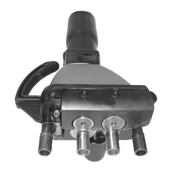
Tightening screws with turning moment 13 Roller (30°) 18 Driver roller (75°) 14 Roller (75°) 22 Slotted nut 17 Driver roller (30°) 23 Cylindrical pin 5 m 6x24 DIN 6325 View of the F300 lock seam stripper from below, the Fig. -
Page 19: Replacing Carbon Brushes
Replacing carbon brushes The motor comes to a standstill when the carbon brushes are worn out. Have the carbon brushes checked and replaced as needed by a trained technician. Note Only use original replacement parts and take note of the information on the rating plate. -
Page 20: Original Accessories And Wearing Parts
Required delivery type (e.g. air mail, courier, express mail, – ordinary freight, parcel post). 4. Send the order to the TRUMPF representative office. For TRUMPF service addresses, see the address list at the end of the document. Original accessories and wearing parts E517EN_03.DOC...
Need help?
Do you have a question about the F 300-2 Plus and is the answer not in the manual?
Questions and answers