
Subscribe to Our Youtube Channel
Related Manuals for Trumpf Track&Trace


Summary of Contents for Trumpf Track&Trace
- Page 1 Installation manual Track&Trace Edition 2020-06-01 TRUMPF Werkzeugmaschinen GmbH + Co. KG, Technische Redaktion Johann-Maus-Straße 2, D-71254 Ditzingen Fon: +49 7156 303 - 0 Internet: http://www.trumpf.com E-Mail: docu.th@de.trumpf.com...
-
Page 3: Table Of Contents
Table of contents Components included Customer checklist for installation prepa- ration Preparing the hall plan Installation of the system Mounting satellites Start-up of preinstalled industrial PC C1105en 2020-06-01 Table of contents... -
Page 4: Components Included
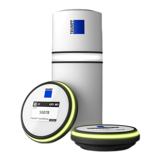
Components included There are different package sizes. The number of satellites and markers differs depending on the package size. Track&Trace components Fig. 94174 Satellite TRUMPF logo (also used as a LED status ring reference point during calibra- tion) Satellite Fig. 94260... - Page 5 USB-C connection (power sup- Ethernet port (power supply ply) and data transmission) Connecting the satellite Fig. 94278 Marker LED status ring TRUMPF logo E-Ink display Marker Fig. 94175 The marker is charged by induction. C1105en 2020-06-01 Components included...
- Page 6 Fastening set for markers Fastening clip Fastening set for markers Fig. 98117 Charging station for markers Components included 2020-06-01 C1105en...
- Page 7 Preinstalled industrial PC Connection to customer's net- Start-up of the service port work Power supply Satellite network connection Preinstalled industrial PC Fig. 96599 C1105en 2020-06-01 Components included...
-
Page 8: Customer Checklist For Installation Preparation
Customer checklist for installation preparation Designation Number Remark Track&Trace components Contents: satellites, operator's man- ual, markers, industrial PC, holders Current hall plan / layout min. 1 Hall plan as background for the user interface (see "Preparing the hall plan", pg. 7) Fastening material (screws, dowels, Depending on Assembly accessories for fixing the... -
Page 9: Preparing The Hall Plan
Preparing the hall plan An up-to-date and suitable hall plan must be available at the commissioning date. A walk-through inspection of the hall is necessary in order to take into consideration the on-site conditions. The hall plan used also serves as a basic map for the localiza- tion in the user interface, and must meet certain requirements. -
Page 10: Installation Of The System
Do-it-yourself holders must not enclose or shield the satel- lite, so that the signal is not interfered with. ■ The TRUMPF logo must always point toward the tracking area. Means, Tools, Materials Brackets for wall, ceiling or free-standing assembly. Drawing ■... - Page 11 ■ Suitable screws and dowels ■ Hammer drill or standard drill ■ Safe ladder or boom lift Fasten satellite Drilled holes Example Fig. 94277 1. Fasten holders to drilled holes in the wall, and fasten the sat- ellite in the holder.
-
Page 12: Start-Up Of Preinstalled Industrial Pc
100 m long or more. The light ring of the satellite must respond. Ø In exceptional cases after consultation with TRUMPF: Connect satellite via USB-C with the power supply. The satellite is automatically switched on as soon as it is connected to the mains. - Page 13 − trumpf.jfrog.io:8081 (TCP) − gitlab.com/TRUMPF-corp/locationTrackingSytem/Develop- ment:443 (TCP) − 185.82.160.50 or tpp-de.tnt.api.trumpf.com − 185.82.163.20 or tpp-sg.tnt.api.trumpf.com − 218.4.161.131 or tpp-cn.tnt.api.trumpf.com − The ports 500 (UDP), 4500 (UDP) and 443 (TCP) − tnt-devops-puppet-server-xe5nibbltusunrkr.eu-cen- tral-1.opsworks-cm.io − The ports 8140, 8142 and 61613 (all TCP) ■...
- Page 14 ■ (2) LAN3 For connection to the satellite network. ■ (3) LAN1 and LAN2 Service or debugging ports for local error identification. If the local network connection of the preinstalled industrial PC is lost, a PC or laptop can be connected to the network via this connection (subnet 172.30.0.0, DHCP must be acti- vated on the device).
Need help?
Do you have a question about the Track&Trace and is the answer not in the manual?
Questions and answers