Advertisement
Quick Links
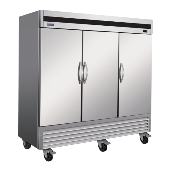
REACH INS-BOTTOM MOUNT
Installation, Operation and Maintenance Manual
Please read this manual completely before attempting to install or operate this equipment.
Notify carrier of damage! Inspect all components immediately. See page 2.
IMPORTANT INFORMATION
READ BEFORE USE
PLEASE SAVE THESE INSTRUCTIONS!
Advertisement

Related Manuals for Kool-It IB27R


Summary of Contents for Kool-It IB27R
- Page 1 REACH INS-BOTTOM MOUNT Installation, Operation and Maintenance Manual Please read this manual completely before attempting to install or operate this equipment. Notify carrier of damage! Inspect all components immediately. See page 2. IMPORTANT INFORMATION READ BEFORE USE PLEASE SAVE THESE INSTRUCTIONS!
-
Page 2: Table Of Contents
Service and Installation Manual CONTENTS RECEIVING & INSPECTING EQUIPMENT .................. 2 SPECIFICATIONS ............................3 INSTALLATION ............................ 4 OPERATION…............................... 5 MAINTENANCE .......................... 7 WIRING DIAGRAM ....................... 9 All rights reserved. Reproduction of this manual without written permission is prohibited. SERIAL NUMBER INFORMATION The serial number of all self-contained refrigerators and freezers is located inside the unit on the left hand side near the top on the wall. -
Page 3: Specifications
SPECIFICATIONS REFRIGERANT R-290 SOLID DOOR REFRIGERATORS V/Hz/Ph FULL MODEL# STORAGE SHELF SHIP LOAD CAPACITY CAPACITY CHARGE WEIGHT NEMA AMPS Cu-ft PLUG Sq-ft IB27R 18.1 1670 3.00 14.0 115/60/1 5-15P 41.6 2380 3.70 IB54R 115/60/1 28.1 5-15P IB81R 66.0 3200 5.29 42.1... -
Page 4: Installation
Service and Installation Manual INSTALLATION Location Units represented in this manual are intended for indoor use only. Be sure the location chosen has a floor strong enough to support the total weight of the cabinet and contents. A fully loaded unit can weigh as much as 1500 pounds. -
Page 5: Operation
Service and Installation Manual OPERATION Do not throw items into the storage area. Failure to heed these recommendations could result in damage to the interior of the cabinet. CAUTION Refrigerated cycle Refrigerators: During the refrigeration cycle, the evaporator fans will run continuously even when one or more doors are open. - Page 6 Service and Installation Manual 1.1 Function of LEDS MODE FUNCTION Compressor enabled Flashing -Programming Phase (flashing with - Anti-short cycle delay enabled Defrost enabled Flashing - Programming Phase (flashing with - Drip time in progress Fans enabled Flashing Fans delay after defrost in progress. An temperature alarm happened 2.
-
Page 7: Maintenance
Service and Installation Manual MAINTENANCE The unit must be turned OFF and disconnected from the power source whenever performing service, maintenance functions or cleaning the refrigerated area. DANGER Refrigerators and Freezers The interior and exterior can be cleaned using soap and warm water. If this isn't sufficient, try ammonia and water or a nonabrasive liquid cleaner. - Page 8 Service and Installation Manual MAINTENANCE Cleaning solutions need to be alkaline based or non-chloride based. Any cleaner containing chlorides will damage the protective film of the stainless steel. Chlorides are commonly found in hard water, salts, and household and industrial cleaners. If cleaners containing chlorides are used, be sure to rinse and dry thoroughly.
-
Page 9: Wiring Diagram
Service and Installation Manual ELECTRICAL DIAGRAM MODEL:IB27R CONDENSER FAN MODEL:IB54R CONDENSER FAN... - Page 10 Service and Installation Manual ELECTRICAL DIAGRAM MODEL:IB81R OVERLOAD PLUG CONTACTOR PROTECTOR LAMP COMPRESSOR CONDENSER THERMOSTAT DISPLAY CURRENT RELAY ROOM EVAP SENSOR DOOR SWITCH MODEL:IB27RG OVERLOAD PROTECTOR PLUG CONDENSER COMPRESSOR LAMP THERMOSTAT DISPLAY CURRENT RELAY STARTING EVAP ROOM DOOR SWITCH LAMP SWITCH CAPACITOR SENSOR...
- Page 11 Service and Installation Manual ELECTRICAL DIAGRAM MODEL:IB54RG OVERLOAD CONTACTOR PLUG PROTECTOR LAMP COMPRESSOR CONDENSER LAMP THERMOSTAT DISPLAY CURRENT RELAY STARTING LAMP SWITCH CAPACITOR DOOR SWITCH EVAP ROOM SENSOR MODEL:IB27F OVERLOAD PROTECTOR PLUG CONTACTOR CONDENSER FAN THERMAL LAMP COMPRESSOR CUT-OFF DOOR SWITCH CURRENT THERMOSTAT DISPLAY...
- Page 12 Service and Installation Manual ELECTRICAL DIAGRAM MODEL:IB54F OVERLOAD PROTECTOR PLUG CONTACTOR LAMP CONTACTOR THERMAL CONDENSER COMPRESSOR CUT-OFF CURRENT THERMOSTAT DISPLAY RELAY STARTING CAPACITOR CAPACITOR EVAP ROOM SENSOR MODEL:IB81FDV CONTACTOR OVERLOAD PROTECTOR POWER THERMAL PLUG CUT-OFF CONDENSER EVAP CONTACTOR COMPRESSOR LAMP CURRENT RELAY STARTING...
- Page 13 Service and Installation Manual ELECTRICAL DIAGRAM MODEL:IB27FG OVERLOAD PROTECTOR PLUG LAMP SWITCH CONDENSER COMPRESSOR DRIVER DOOR THERMOSTAT SWITCH LAMP DISPLAY CURRENT RELAY STARTING CAPACITOR ROOM EVAP SENSOR MODEL:IB54FG OVERLOAD LAMP PROTECTOR PLUG SWITCH CONDENSER COMPRESSOR DRIVER DOOR SWITCH CURRENT LAMP THERMOSTAT DISPLAY RELAY STARTING...
- Page 14 Service and Installation Manual WIRING DIAGRAM MODEL: IB27R...
- Page 15 Service and Installation Manual WIRING DIAGRAM MODEL: IB 27RG...
- Page 16 Service and Installation Manual WIRING DIAGRAM MODEL: IB27F...
- Page 17 Service and Installation Manual WIRING DIAGRAM MODEL: IB 54R...
- Page 18 Service and Installation Manual WIRING DIAGRAM MODEL: IB54RG...
- Page 19 Service and Installation Manual WIRING DIAGRAM MODEL: IB54F...
- Page 20 Service and Installation Manual WIRING DIAGRAM MODEL: IB81R...
- Page 21 Service and Installation Manual WIRING DIAGRAM MODEL: IB 81FDV...
- Page 22 RRRRRR Service and Installation Manual ELECTRICAL DIAGRAM MODEL:IB27FG THERMOSTAT DISPLAY...
- Page 23 Service and Installation Manual ELECTRICAL DIAGRAM MODEL:IB54FG THTH THERMOSTAT DISPLAY...
- Page 24 Service and Installation Manual IKON WARRANTY Two Year Parts & Labor Warranty MVP Group (IKON) warrants, to the original purchaser, all of its new equipment to be free from defects in material and workmanship, under normal use and maintenance service, for a period of two (2) years from the date of original purchase or 15 months after shipment date from the manufacturer, whichever occurs first.
Need help?
Do you have a question about the IB27R and is the answer not in the manual?
Questions and answers