Advertisement
By
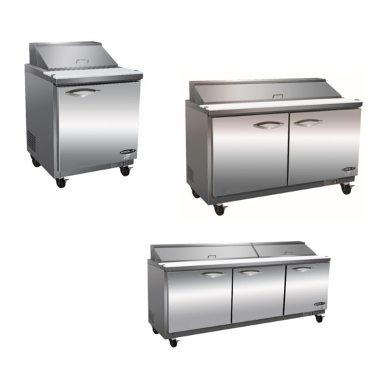
Pizza Prep Tables
Sandwich/Salad Units
Under-counter Refrigerators and Freezers
Worktop Refrigerators and Freezers
Service, Installation and Care Manual
Please read this manual completely before attempting to install or operate this equipment.
Notify carrier of damage! Inspect all components immediately.
IMPORTANT INFORMATION
READ BEFORE USE
PLEASE SAVE THESE INSTRUCTIONS!
Advertisement

Related Manuals for Kool-It Ikon KSP29


Summary of Contents for Kool-It Ikon KSP29
- Page 1 Pizza Prep Tables Sandwich/Salad Units Under-counter Refrigerators and Freezers Worktop Refrigerators and Freezers Service, Installation and Care Manual Please read this manual completely before attempting to install or operate this equipment. Notify carrier of damage! Inspect all components immediately. IMPORTANT INFORMATION READ BEFORE USE PLEASE SAVE THESE INSTRUCTIONS!
- Page 2 Service and Installation Manual COMMECIAL REFRIGERATOR SAFETY Your safety and the safety of others are very important. We have provided many important safety messages in this manual and on your appliance. Always read and obey all safety messages. Our product instructions will be uploaded on our company official website. This is the Safety Alert Symbol.
- Page 3 Service and Installation Manual The key for appliance electric box should be safe kept by qualified persons in order to avoid a hazard WARNING: Keep ventilation openings, in the appliance enclosure or in the built-in structure, clear of obstruction. WARNING: Do not use mechanical devices or other means to accelerate the defrosting process, other than those recommended by the manufacturer.
-
Page 4: Table Of Contents
Service and Installation Manual CONTENTS RECEIVING & INSPECTING EQUIPMENT .................... 4 SPECIFICATIONS ............................5 INSTALLATION ..............................6 OPERATION ................................7 MAINTENANCE ............................9 WIRING DIAGRAM ........................11 All rights reserved. Reproduction without written permission is prohibited. SERIAL NUMBER INFORMATION The serial number of all self-contained refrigerators and freezers is located inside the unit on the left hand side near the top on the wall. -
Page 5: Specifications
Service and Installation Manual SPECIFICATION SANDWICH/SALAD UNITS STORAGE SHELF SHIP CAPACITY CAPACITY CHARGE WEIGHT NEMA MODEL# V/Hz/Ph AMPS Size HP Cu-ft Sq-ft PLUG KSP29 115/60/1 3200 5-15P KSP48 115/60/1 5400 5-15P KSP60 115/60/1 15.5 5800 10.6 5-15P KSP72 115/60/1 6200 10.6 5-15P SANDWICH/SALAD UNITS... -
Page 6: Installation
Service and Installation Manual INSTALLATION Location Units represented in this manual are intended for indoor use only. Be sure the location chosen has a floor strong enough to support the total weight of the cabinet and contents. A fully loaded unit can weigh as much as 1500 pounds. -
Page 7: Operation
Service and Installation Manual OPERATION Do not throw items into the storage area. Failure to heed these recommendations could result in damage to the interior of the cabinet. CAUTION Refrigerated cabinets Temperature range for the internal cabinets is 33°F to 40°F for all food prep units, undercounter and worktop refrigerators, and -7°F to -3°F for undercounter and worktop freezers. - Page 8 Service and Installation Manual 1.1 Function of LEDS MAIN FUNCTIONS 2.1 HOW TO SEE THE SETPOINT 1. Push and immediately release the SET key: the display will show the set point value. 2. Push and immediately release the SET key or wait for 5 seconds to display the sensor value again.
-
Page 9: Maintenance
Service and Installation Manual MAINTENANCE The power switch must be turned OFF and the unit disconnected from the power source whenever performing service, maintenance functions or cleaning the refrigerated area. DANGER Refrigerators and Freezers The interior and exterior can be cleaned using soap and warm water. If this isn't sufficient, try ammonia and water or a nonabrasive liquid cleaner. - Page 10 Service and Installation Manual MAINTENANCE Cleaning solutions need to be alkaline based or non-chloride based. Any cleaner containing chlorides will damage the protective film of the stainless steel. Chlorides are commonly found in hard water, salts, and household and industrial cleaners. If cleaners containing chlorides are used, be sure to rinse and dry thoroughly.
-
Page 11: Wiring Diagram
Service and Installation Manual WIRING DIAGRAM MODEL: KUC27 PLUG DOOR OVERLOAD SWITCH PROTECTOR COMPRESSOR CONDENSEN POWER THERMOSTAT DISPLAY CURRENT RELAY STARTING CAPACITOR EVAP ROOM EVAP SENSOR... - Page 12 Service and Installation Manual WIRING DIAGRAM MODEL: KUC48/KUC60 PLUG OVERLOAD DOOR PROTECTOR SWITCH CONDENSEN COMPRESSOR THERMOSTAT DISPLAY POWER CURRENT RELAY STARTING EVAP CAPACITOR ROOM EVAP SENSOR MODEL: KUC72 PLUG OVERLOAD PROTECTOR THERMOSTAT DISPLAY CONDENSEN COMPRESSOR DOOR SWITCH ROOM EVAP POWER SENSOR CURRENT RELAY...
- Page 13 Service and Installation Manual WIRING DIAGRAM MODEL: KPP44 THERMOSTAT DISPLAY PLUG OVERLOAD PROTECTOR EVAP CIRCUITALION ROOM CONDENSER FAN MOTOR SENSOR FAN MOTOR COMPRESSOR t ℃ PTC STARTER MODEL: KPP67 THERMOSTAT DISPLAY OVERLOAD PLUG PROTECTOR EVAP ROOM SENSOR CIRCUITALION CONDENSER COMPRESSOR FAN MOTOR FAN MOTOR CURRENT...
- Page 14 Service and Installation Manual WIRING DIAGRAM MODEL: KPP93 THERMOSTAT DISPLAY OVERLOAD PLUG PROTECTOR EVAP ROOM SENSOR COMPRESSOR CIRCUITALION CONDENSER FAN MOTOR FAN MOTOR CURRENT RELAY STARTING CAPACITOR MODEL: KSP29/ KSP29M THERMOSTAT DISPLAY PLUG OVERLOAD PROTECTOR EVAP ROOM CIRCUITALION SENSOR CONDENSER FAN MOTOR FAN MOTOR COMPRESSOR...
- Page 15 Service and Installation Manual WIRING DIAGRAM MODEL: KSP48/ KSP60/ KSP48M/ KSP60M THERMOSTAT DISPLAY PLUG OVERLOAD PROTECTOR EVAP ROOM CONDENSER CIRCUITALION SENSOR FAN MOTOR FAN MOTOR COMPRESSOR t ℃ PTC STARTER MODEL: KSP72/ KSP72M THERMOSTAT DISPLAY OVERLOAD PLUG PROTECTOR EVAP ROOM CONDENSER CIRCUITALION SENSOR...
- Page 16 Service and Installation Manual WIRING DIAGRAM MODEL: KUC27F PLUG THERMAL OVERLOAD CUT-OFF PROTECTOR DOOR COMPRESSOR SWITCH CONDENSEN POWER THERMOSTAT DISPLAY EVAP CURRENT STARTING RELAY CAPACITOR ROOM EVAP SENSOR KUC48F/ KUC60F MODEL: PLUG THERMAL CUT-OFF OVERLOAD PROTECTOR DOOR SWITCH COMPRESSOR CONDENSEN POWER THERMOSTAT DISPLAY STARTING...
- Page 17 Service and Installation Manual WIRING DIAGRAM MODEL: KUC72F THERMAL OVERLOAD PLUG CUT-OFF PROTECTOR DOOR SWITCH COMPRESSOR CONDENSEN POWER THERMOSTAT DISPLAY CURRENT STARTING RELAY CAPACITOR EVAP ROOM EVAP SENSOR...
- Page 18 Service and Installation Manual WIRING DIAGRAM MODEL: KUC27...
- Page 19 Service and Installation Manual WIRING DIAGRAM MODEL: KUC48/KUC60...
- Page 20 Service and Installation Manual WIRING DIAGRAM MODEL: KUC72...
- Page 21 Service and Installation Manual WIRING DIAGRAM MODEL: KSP29 / KSP29M...
- Page 22 Service and Installation Manual WIRING DIAGRAM MODEL: KSP48 / KSP60 / KSP48M / KSP60M...
- Page 23 Service and Installation Manual WIRING DIAGRAM MODEL: KSP72 / KSP72M...
- Page 24 Service and Installation Manual WIRING DIAGRAM MODEL: KPP44...
- Page 25 Service and Installation Manual WIRING DIAGRAM MODEL: KPP67...
- Page 26 Service and Installation Manual WIRING DIAGRAM MODEL: KPP93...
- Page 27 Service and Installation Manual WIRING DIAGRAM MODEL: KUC26F...
- Page 28 Service and Installation Manual WIRING DIAGRAM MODEL: KUC27F...
- Page 29 Service and Installation Manual WIRING DIAGRAM MODEL: KUC48F/KUC60F...
- Page 30 WIRING DIAGRAM MODEL: KUC72F...
- Page 31 Service and Installation Manual IKON WARRANTY Two Year Parts & Labor Warranty MVP Group (IKON) warrants, to the original purchaser, all of its new equipment to be free from defects in material and workmanship, under normal use and maintenance service, for a period of two (2) years from the date of original purchase or 15 months after shipment date from the manufacturer, whichever occurs first.
Need help?
Do you have a question about the Ikon KSP29 and is the answer not in the manual?
Questions and answers