Advertisement
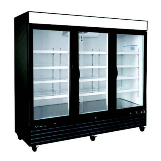
Glass Door Merchandiser Freezer
Service, Installation and Care Manual
Please read this manual completely before attempting to install or operate this equipment.
Notify carrier of damage! Inspect all components immediately.
KGF-23
KGF-48
IMPORTANT INFORMATION
READ BEFORE USE
PLEASE SAVE THESE INSTRUCTIONS!
3560 NW 56th Street
Fort Lauderdale, FL 33309
Tel.: 786.600.4687 / Toll Free: 844.218.8477
Fax.: 786.661.4100
sales@mvpgroupcorp.com
5659 Royalmount Avenue
Montreal, Qc, Canada H4P 2P9
Tel.: 514.737.9701 / Toll Free: 888.275.4538
Fax.: 514.342.3854 / Toll Free: 877.453.8832
www.mvpgroupcorp.com
KGF-72DV
Printed 05/2020
Advertisement


Need help?
Do you have a question about the KGF-48 and is the answer not in the manual?
Questions and answers