Table of Contents
Advertisement
Available languages
Available languages
Quick Links
Advertisement
Table of Contents

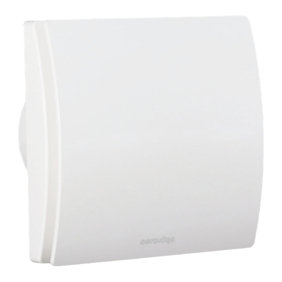
Summary of Contents for aerauliqa Quantum EX 100 HT
- Page 1 Quantum EX 100 HT MANUALE ISTRUZIONI INSTRUCTION MANUAL...
- Page 2 Leggere questo manuale con attenzione prima di usare il prodotto e conservarlo in un posto sicuro così da poterlo consultare all’occorrenza. Il prodotto è costruito a regola d’arte e nel rispetto delle normative vigenti in materia di apparecchiature elettriche e deve essere installato da personale tecnicamente qualificato. La ditta costruttrice non si assume responsabilità...
-
Page 3: Caratteristiche Tecniche
• Non ostruire la griglia di aspirazione o di espulsione per garantire l’ottimale passaggio dell’aria. • Assicurare un adeguato rientro dell’aria nel locale, nel rispetto del regolamento vigente, al fine di garantire il corretto funzionamento dell’apparecchio. • Qualora nell’ambiente in cui è installato il prodotto sia presente un apparecchio funzionante a combustibile (scaldacqua, stufa a metano etc., di tipo non a “camera stagna”), è... -
Page 4: Smaltimento E Riciclaggio
SETTAGGIO VELOCITÀ Le possibili configurazioni di velocità minima, intermedia e massima sono rappresentate dai grafici di Fig.14 e selezionabili tramite gli interruttori come indicato in tabella DIP SWITCH A (Fig.15). VELOCITA’ MINIMA CONTINUA Nel momento dell’accensione, l’unità funziona alla velocità minima continua. VELOCITA’... - Page 5 Read this manual carefully before using the product and keep it in a safe place for reference. This product was constructed up to standard and in compliance with regulations relating to electrical equipment and must be installed by technically qualified personnel. The manufacturer assumes no responsibility for damage to persons or property resulting from failure to observe the regulations contained in this booklet.
-
Page 6: Technical Specifications
• Install the product so that the impeller is not accessible from the air outlet side as verified by contact with the Test Finger (test probe “B” of the norm EN61032) in compliance with the current safety regulations. • Window installation In case of window installation it is necessary to use the appropriate window kit, which is not included. -
Page 7: Disposal And Recycling
SPEED SETTING The possible configurations of the minimum, intermediate and maximum speeds are shown in the graphs of Fig.14 and selectable through the switches as indicated in the DIP SWITCH A Table (Fig.15). MINIMUM CONTINUOUS SPEED Upon power-up, the unit runs at the minimum continuous speed. INTERMEDIATE SPEED The unit runs automatically at the intermediate speed. - Page 8 INSTALLAZIONE - INSTALLATION (Fig.1) soffitto vetro (kit a richiesta) parete / pannello ceiling window (kit on demand) wall espulsione diretta canalizzazione direct exhausting ducted MONTAGGIO E COLLEGAMENTI ELETTRICI - MOUNTING AND WIRING DIAGRAM FIG.2: CONTENUTO IMBALLO QDMEV click! 2 NUOVE FIGURE: ASSEMBLAGGIO STATORE (DA INSERIRE TRA LE FIG.
- Page 9 NE 2 - 3- 4 - 5 OK NE 6 ELIMINARE LA NOTA CON RIFERIMENTO AL QUANTUM AX 150 UIRE LA SCRITTA QUANTUM AX 100 CON LA SCRITTA QDMEV100 IMMAGINE 10A Quantum EX 100 HT = ø99mm IMMAGINE 1: CAVO A PARETE VERIFICARE LA POSSIBILITA' DI LASCIARE L'INSTALLAZ 4xø5mm...
- Page 10 IMMAGINE 12A IMMAGINE 12B IMMAGINE 7 AZIONE A FINESTRA IMMAGINE 7 CAVO A PARET CAVO SOTTOTRACCIA E A FINESTRA RECESSED CABLE ENTRY 4 x ø 5 mm A FINESTRA CAVO A PARETE IMMAGINE 8A - 9 ESTRA AL QUANTUM AX 150 H03VV-F ;...
- Page 11 • Quando si esegue il collegamento ai morsetti, non avvitare troppo le viti: coppia massima 0,15Nm. • When wiring to the PCB terminals, do not overtighten the screws: maximum torque 0,15Nm. CONFIGURATION (default) CONFIGURATION QUANTUM EX Through-Wall QUANTUM EX Through-Wall Air-flow - m Air-flow - m m3/h...
- Page 12 CONFIGURATION CONFIGURATION QUANTUM EX Through-Wall QUANTUM EX Through-Wall Air-flow - m Air-flow - m m3/h m3/h DIP SWITCH A Setting Configuration (Fig.14) default DIP SWITCH B • Questa immagine mostra i Dip Switch su circuito humidistat elettronico. disattivato/disabled Attenzione: Durante il settaggio l’unità deve essere disconnessa dall’alimentazione principale.
- Page 13 MANUTENZIONE / PULIZIA - MAINTENANCE / CLEANING...
- Page 14 Direttiva ErP - Regolamenti 1253/2014 - 1254/2014 ErP Directive Regulations 1253/2014 - 1254/2014 a) Marchio - Mark AERAULIQA QUANTUM EX 100 HT b) Modello - Model c) Classe SEC - SEC class kWh/m c1) SEC climi caldi - SEC warm climates...
- Page 16 - www.aerauliqa.com - info@aerauliqa.it Aerauliqa S.r.l. si riserva il diritto di modificare/apportare migliorie ai prodotti e/o alle istruzioni di questo manuale in qualsiasi momento e senza preavviso. Aerauliqa S.r.l. reserves the right to modify/make improvements to products and/or this instruction manual at any time and without prior notice.


Need help?
Do you have a question about the Quantum EX 100 HT and is the answer not in the manual?
Questions and answers