
Related Manuals for Triax 692855


Summary of Contents for Triax 692855
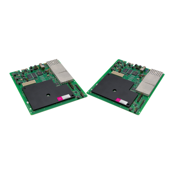
- Page 1 Configuration guide TDH 800 – QAM output module Model Item no. TDH 800 – QAM output module 692855 692856 triax.com 891576A Version 08 - 2013...
-
Page 2: Table Of Contents
Contents Contents Introduction............................... 3 System requirements ............................3 Computer minimum requirements ......................3 Static IP address ............................3 Physical connection to headend ....................... 3 Service tool ............................... 4 Overview ............................... 5 Icons................................5 Tabs ................................6 Misc. Buttons ............................. 6 Configuring CA modules .......................... -
Page 3: Introduction
Introduction Introduction Introduction Introduction This document describes the configuration of the QAM Output module for the TDH 800 headend. This document describes the configuration of the QAM Output module for the TDH 800 headend. Physical installation of the module is described in the TDH 800 main unit installation guide. -
Page 4: Service Tool
Introduction Service tool 1. Open a web browser window. 2. Enter ‘http://192.168.0.100’ in the web address field. 3. Press Enter. 4. Enter the password. 5. Press the Log in button. Note: Password = ‘triax1234’ when the service tool is opened for the first time. The Keep me logged in checkbox overrides the system’s automatic time out function, which is activated after 20 minute’s inactivity. -
Page 5: Overview
Introduction Overview Communication icon Tabs Misc Buttons System icon Configuration buttons Icons Indicates whether the service tool is communicating correctly with the headend unit. Green The service tool and headend are communicating correctly. The service tool and headend are NOT communicating correctly. -
Page 6: Tabs
Introduction Tabs Accesses the various tabs used to configure the headend’s input and output modules. System The service tool’s ‘home’ window. Provides system overview information and configuration activation/control. Input Tab for configuring input modules and services. Refer to input module manuals for information. CA Modules Tab for configuring CI modules and CA cards. -
Page 7: Configuring Ca Modules
Configuring CA modules Configuring CA modules Pre-requisites The headend is running, the CA module has been placed in the output module, the output module is inserted in the headen, and the TDH Service Tool is connected to the headend. See the TDH 800 Headend User Guide for information on inserting the output module into the TDH 800 headend. - Page 8 Configuring CA modules Apply button Tabs CA module button Common interface Service list area Submit button Reset CAM button Status area The CA Module setup window is displayed, initially containing default values. 3. Specify the speed of the CI card in the Card speed drop-down list. 4.
- Page 9 Configuring CA modules The Filter options window is set by default to descramble all audio PIDs associated with the service. 8. Enable the Descramble non audio/video PIDs checkbox to descramble all PIDs associated with the service, that are neither audio, or video related. 9.
-
Page 10: Resetting
Configuring CA modules language is selected. 13. Press the Submit button in the CA Module setup window. The service(s) selected in now listed. 14. Press the Apply button. The following confirmation is displayed. Resetting It may be necessary to reset the CA module if it malfunctions. 1. -
Page 11: Modifying
Configuring CA modules 2. Press the Reset CAM button. 3. Press the Yes button. The CA module will be reset and service transmission through it will be temporally interrupted. The ER checkbox can alternatively be enabled to automatically reset CA modules, see above. Modifying 1. -
Page 12: Deleting
Configuring CA modules Deleting 1. Press the Delete button of the CA module to be removed. A confirmation popup is displayed. 2. Press Yes on the confirmation popup. -
Page 13: Configuring Qam Output Modules
Configuring QAM output modules Configuring QAM output modules Pre-requisites The headend is running, the output module is in position, and the TDH Service Tool is connected to the headend. See the TDH 800 Headend User Guide for information on inserting the output module into the TDH 800 headend. - Page 14 Configuring QAM output modules Uncheck 3. Remove the check from the Disabled output checkbox. Channel, channel QAM modules can be configured either by using the pre-defined spacing and frequency channel plans, or through manual specification. Pre-defined 1. Select the required Channel plan. 2.
- Page 15 Configuring QAM output modules 3. Check the Select service/s checkbox for the required services. 4. (Optional) Specify an Output SID for the selected services. 5. (Optional) Specify a collective name (Mux) for the selected services in the Mux name field. 6.
- Page 16 Configuring QAM output modules Additional settings 4. Make (if required) additional configuration changes in the following fields/drop-down lists in the configuration window: RF level correction Symbol rate QAM mode Transmission mode Note: The Manual SDT version checkbox is only used in special circumstances and it is recommended that it remains ‘unchecked’.
- Page 17 Configuring QAM output modules 3. Press the Apply button. The following confirmation is displayed. The services selected are visible in the Channel list tab.
-
Page 18: Modifying
Configuring QAM output modules The remaining slots on the output module can now be configured in the same manner. Modifying 1. Press the Setup button for the output module to be modified. 2. Make the desired changes. 3. Press the Update button. 4. - Page 19 Triax Date: October 2012 Signature: triax.com/support Copyright © 2016 TRIAX. All rights reserved. The TRIAX Logo and TRIAX, TRIAX Multimedia are registered trademarks or trademarks of the TRIAX Company or its affiliates. Your ultimate connection 08-2013 All specifications in this guide are subject to change without further notice.
Need help?
Do you have a question about the 692855 and is the answer not in the manual?
Questions and answers