Triax TDH 800 User Manual
Headend unit
Hide thumbs
Also See for TDH 800:
- User manual (36 pages) ,
- Configuration manual (19 pages) ,
- Configuration manual (12 pages)
Table of Contents
Advertisement
Quick Links
Advertisement
Table of Contents

Related Manuals for Triax TDH 800


Summary of Contents for Triax TDH 800
- Page 1 User guide TDH 800 – Headend Unit – Art. 692890 891572 | EN...
-
Page 2: Table Of Contents
Contents Contents Safety Precautions ................................4 Environment .................................. 4 Power supply ................................4 Weight .................................... 4 Earth ....................................4 Disposal ..................................4 Introduction..................................5 Box contents ................................. 5 Components .................................. 6 Headend installation ................................ 7 Mounting ..................................7 Ventilation requirements ............................7 Power/Earth ................................ - Page 3 Contents Computer minimum requirements ........................13 Static IP address ..............................13 Physical connection to headend .......................... 13 Service tool..................................14 Overview ..................................15 Icons ..................................15 Tabs ..................................16 Misc. Buttons ................................16 Administration ................................17 Language ................................. 17 Location ................................... 17 Time zone ................................
-
Page 4: Safety Precautions
Headend overview Safety Precautions Operating temperature -10 C to +50 C. Environment Storage temperature -20 C to + 70 C. Max. Operating humidity 80% (RH). Max. Storage humidity 90% (RH). The input voltage must be 190-264 VAC. ~ 45/65 Hz / 280 W (Max). Power supply Use only power connections installed by professionals. -
Page 5: Introduction
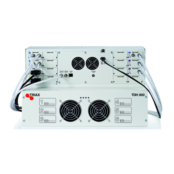
Headend overview Introduction The TDH800 headend accommodates up to 16 input modules and 6 quad output modules. 24 RF Channels are accommodated. All incoming signals from input modules initially arrive in a ‘pool’, where conversion to defined output signals occurs, after which the converted signals are fed to output modules. -
Page 6: Components
Headend Overview Components Input slots (16 in total) Ventilation fans Earth terminal Power input RF output Distributes the RF channels from the output modules using an F-connector. Test point -20 dB RF test point of output (-20 dB). Configuration port Ethernet configuration port for setting up the headend unit. -
Page 7: Headend Installation
Headend Installation Headend installation The headend can be mounted either on a system rack or directly to a Mounting wall. 1. Attach the mounting brackets to the headend with the supplied screws. Installation Bracket position Rack At front of headend. Wall At rear of headend. -
Page 8: Input Modules
Input modules 16 input modules can be installed in the headend. Input modules Input module types Each input module is identified through use of a specific coloured label. The label also indicates the module type’s name and associated item number. The remainder of the label is used for noting post- installation module information. -
Page 9: Attaching Cables
Input modules Attach the signal cables to the ‘IN’ connector on the input module. Attaching cables Note: Ensure that enough cable is available for relocating input modules to alternate input slots at a later date. Signals can be looped between DVB-S/S2 input modules: Looping cables 1. -
Page 10: Output Modules
Output modules Six output modules, each consisting of four RF channels can be Output modules installed. Output module types Each output module is identified through use of a specific coloured label. The label also indicates the module type’s name and associated item number. -
Page 11: Removing Output Module
Output modules 3. Insert smart cards (if relevant). Insert the service provider’s smartcard into the CA module. Insert the CA module into either of the available slots in the output module. 4. Push the output module into an available output slot. 5. -
Page 12: System Monitoring
System monitoring System Monitoring Four LEDs are placed at the top of the output section of the headend unit, LEDs two of which provide information on the state of the headend. The LEDs are named (from left to right): System Status Tuner Status LED3 LED4... -
Page 13: Headend Configuration
Headend configuration Headend configuration The TDH800 headend needs to be configured before it can be used. System requirements Computer minimum A computer meeting the following minimum requirements is required for requirements configuring the headend. Operating system Windows XP or above Browser Windows Internet Explorer version 6.0 or equivalent... -
Page 14: Service Tool
Overview 1. Open a web browser window. Service tool 2. Enter ‘http://192.168.0.100’ in the web address field. 3. Press Enter. 4. Enter the password. 5. Press the Log in button. Note: Password = ‘triax1234’ when the service tool is opened for the first time. The Keep me logged in checkbox overrides the system’s automatic time out function, which is activated after 20 minute’s inactivity. -
Page 15: Overview
Overview Overview Communication icon Tabs Misc. Buttons System icon Configuration buttons Icons Indicates whether the service tool is communicating correctly with the headend unit. Green The service tool and headend are communicating correctly. The service tool and headend are NOT communicating correctly. -
Page 16: Tabs
Overview Tabs Accesses the various tabs used to configure the headend’s input and output modules. System The service tool’s ‘home’ window. Provides system overview information and configuration activation/control. Input Tab for configuring input modules and services. Refer to input module manuals for information. CA Modules Tab for configuring CI modules and CA cards. -
Page 17: Administration
General setting administration Administration The system language, locale, and time zone must be specified for the headend unit. It is also necessary to specify IP addresses for headends which are located on a distribution network. Language 1. Press the Admin button at the top right-hand corner of the System window. -
Page 18: Time Zone
General setting administration 3. Open the Current location drop-down list. 4. Select the country where the headend is located 5. Press the OK button. Time zone 1. Press the Admin button at the top right-hand corner of the System window. 2. -
Page 19: Licences
2. Expand the Licence handling area. 3. Contact Triax Sales and provide the contents of the serial number and unique ID fields. 4. Enter the code provided by Triax Sales into the Activation key field. 5. Press the Activate button. 6. Press the OK button. -
Page 20: Ip Addresses
General setting administration IP addresses It may be necessary to specify specific IP addresses for the headend to avoid network IP address conflicts. Note: Headend IP addresses can be reset to factory default settings if required. This is done via the ID switch located on the headend unit. 1. -
Page 21: Viewing System Log
General setting administration Note: Changes to IP addresses only take effect when the headend has been rebooted. It is possible to save log files for viewing headend actions. Viewing system log 1. Expand the System maintenance area. 2. Press the Save log button. 3. -
Page 22: Firmware
Triax home page, Updating www.Triax.com and then applied to the headend. Always read the release notes to determine whether the headend would benefit from available firmware updates or not. 1. Expand the System maintenance area. 2. Press the Change button. - Page 23 General setting administration 8. Press the Set active button. 9. Select the Replace all radio button to update all of the headend’s firmware, i.e. modules, system controller and user interface. (Recommended) 10. Select the Update old packages radio button to only update out- dated modules.
-
Page 24: Viewing System Information
General setting administration 13. Logon to the system tool and make any further changes. Cleaning up Firmware to be deleted 1. Select the firmware updates to be removed from the system tool. 2. Press the Delete package button. Viewing system Detailed information is available on headend units. - Page 25 Any headend system errors Name and associated software version of input and output modules Note that the software versions installed on the TDH 800 main unit and each input/output module must be identical. Update the software for the entire TDH 800 headend (including input/output modules) if this is not the case.
-
Page 26: Managing Configuration Files
Managing configuration files Managing configuration files Creating 1. Select the System tab. 2. Select the New button. An empty configuration file is created and listed in the configuration list area. Activating 1. Select the System tab. 2. Select the configuration that is to be actively used on the headend. 3. -
Page 27: Deleting
Managing configuration files Deleting 1. Select the System tab. 2. Highlight the configuration file to be deleted. 3. Press the Delete button. -
Page 28: Saving
Managing configuration files Saving Headend configuration files can, if desired, be saved on a computer. This simplifies the process of configuring additional headends. A saved configuration file can be used on headends that do not contain exactly the same modules. It will, however, be necessary to reconfigure/delete/add the modules that differ between the initial headend and that being configured. -
Page 29: Uploading
Managing configuration files 7. Press the Save button. Uploading Configuration files previously saved on a computer can be transferred to the service tool to simplify the configuration process. Any module differences will need to be manually configured. 1. Select the System tab. 2. -
Page 30: Configuring Network
Note that Network ID’s and Network names are required for both DVB-T and DVB-C. Network ID Provided by the TDH 800 Service Tool. This cannot be modified. Network name Provided by the TDH 800 Service Tool. - Page 31 Configuring network be used. It is recommended that this checkbox is left unchecked. Enable HD LCN Check the Enable HD LCN checkbox if an HD channel is to take precedence over the same channel in SD mode. LCN numbers for both the SD and HD channels need to be specified in the LCN number field and HD LCN number fields.
- Page 32 8783 Hornsyld web: www.triax.dk Denmark DECLARATION OF CONFORMITY TRIAX confirms that the product conforms to relevant EEC harmonised standards and consequently can carry the CE-mark. Relevant harmonised standards: DE/EN 60728-2 2010, DS/EN 60728-11 2010 and DS/EN 50083-2 2006 This document is only valid with the signature of the person responsible for CE-marking by...
Need help?
Do you have a question about the TDH 800 and is the answer not in the manual?
Questions and answers