
Related Manuals for Triax CCAV 300


Summary of Contents for Triax CCAV 300
- Page 1 Assembly Instruction CCAV 300 Model Item no. CCAV 300 325129 Version Date 03/2017...
-
Page 2: Table Of Contents
o n t e n t s 1 Safety regulations and notes ................3 2 General information ..................4 2.1 Scope of delivery ................4 2.2 Meaning of the symbols used ............... 4 2.3 Technical specifications ............... 4 2.4 Description ..................5 Display of the control unit software version ..........5 3 Installation ......................6 3.1 Installing the cassette ................6 3.2 EMC regulations ................7 3.3 Overview of the cassette ..............8 3.4 Connecting the cassette . -
Page 3: Safety Regulations And Notes
• Test the software versions of the head-end station and the cassette and update them if necessary. The current software versions can be found at "www.triax.com". Take action to prevent static discharge when working on the device! Electronic devices should never be disposed of in the household rubbish. In... -
Page 4: General Information
e n e r a l i n f o r m a t i o n 2.1 s C o p e d e l i v e ry 1 CCAV 300 cassette 1 CD (assembly instructions) 1 Brief assembly instructions 2.2 m e a n i n g t h e s ym b o l s u s e d... -
Page 5: Description
When the head-end station is switched on, the two-line LC display shows the software version of the control unit. To operate this cassette the software ver- sion of the control unit must be "V 45" or higher. You can find the current op- erating software for the control unit and the cassette, the software "BE-Flash" and the current assembly instructions on the website "www.triax.com". i s p l ay t h e C o n t r o l u n i t s o f t wa r e v e rs i o n... -
Page 6: Installation
n s t a l l a t i o n 3.1 i n s ta l l i n g t h e C a s s e t t e – Ensure the head-end station is mounted so it will not be able to vibrate. Avoid, for example, mounting the head-end station onto a lift shaft or any other wall or floor construction that vibrates in a similar way. -
Page 7: Emc Regulations
3.2 emC r e g u l at i o n s To comply with the current EMC regulations, it is necessary to connect the lines leading in and out of the head-end station using cable terminals. When mounting the cassette in a head-end station which is installed in a 19" cabinet, make sure the connections leading in and out for the 19" cabinet are made using cable terminals. The attenuation of shielding of the connection lines for ASI and antenna must meet the requirements for "Class A". CLASS • Insert the required number of cable terminals in the openings provided in the head-end station or in the 19" cabinet. Tighten the nuts of the cable terminals until the teeth on the lock washers put un- der have penetrated the exterior coating and a good connection is made between the housing / 19" cabinet and cable terminals. - 7 - CCAV 300... -
Page 8: Overview Of The Cassette
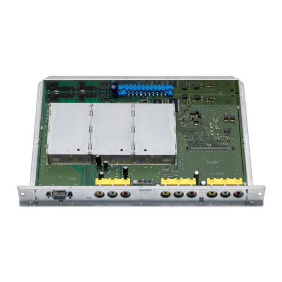
3.3 o v e rv i e w t h e C a s s e t t e Inputs of channel strip "A" Audio input "right" Audio input "left", "mono" Video input Inputs of channel strip "B" Audio input "right" Audio input "left", "mono" Video input Inputs of channel strip "C" Audio input "right" Audio input "left", "mono" Video input D-SUB socket "RS 232" The operating software of the cassette can be updated via the 9-Pin D-SUB socket "RS 232" using a PC or notebook and the software "BE-Flash". You can find the current operating software on the website "www.mygss. eu". 3.4 C o n n e C t i n g t h e C a s s e t t e • Connect the peripheral devices to the cinch input sockets... -
Page 9: The Control Unit At A Glance
C o n t r o l u n i t g l a n C e 4.1 m e n u i t e m s Program the cassette using the buttons on the control unit of the head-end sta- tion. The two-line display of the control unit then shows the menus. The parameters and functions to be set are underlined. Use the button to select the following main menu items: – Cassette – Channel strip (modulator) – RF output level, BE-Remote V 45 switching the modulator on / off please wait . -
Page 10: Programming
r o g r a m m i n g 5.1 p r e pa r at i o n • Connect the test receiver to the RF output or the test output of the head-end station. • Set the output channels / output frequencies of the cassette (page 16) and 16) and ) and adjust the test receiver to the respective channel / frequency. • Switch on the modulator if necessary (page 14). • Measure the output levels of the channel strips and adjust them to a uniform output level (page 17). - 10 - CCAV 300... -
Page 11: Programming Procedure
5.2 p ro g r a m m i n g pro C e d u r e Ein / On BE–Remote V 45 please wait … t > 10 s Bx 1A TWIN-SAT Böx 4 TWIN-SAT Box 1 Box 2 .... -
Page 12: Programming The Cassette
5.3 p r o g r a m m i n g t h e C a s s e t t e —> Pressing the button for longer than 2 seconds cancels the programming procedure. This takes you back to the program item "Selecting the cassette" from any menu. Any entries that have not been saved are reset to the previous settings. —> Entries in the menus can be saved by pressing the key. You are taken back to the "Selecting the cassette" menu item. —> Pressing the button returns to the previous menus. • Switch on the head-end station. Ein / On BE–Remote V 45 please wait …... -
Page 13: Selecting The Channel Strip
—> The "Selecting the channel strip" – "Bx 1A" menu is activated. e l e C t i n g t h e C h a n n e l s t r i p Bx 1A • Use to select the channel strip (modulator) "A", "B" or "C" to be set. —> The display shows e.g. the menu Bx 1A 3AV "Bx 1" stands for slot 1, "A" stands for channel strip "A" "3AV" type of cassette "C08"... -
Page 14: Rf Output Level
o u t p u t l e v e l In this menu you can set the RF output levels of the channel strips "A", "B" and "C" to the same values and switch on or off the modulator of the channel strip. Bx 1A MODULATOR Level • Measure and note down the output level of channel strip "A". • Activate menu item "Selecting the channel strip" using the button and select channel strip "B". • Activate the "MODULATOR Level" menu by pressing the button. • Measure and note down the output level of channel strip "B". • Repeat this procedure for channel strip "C". • Select the channel strips with the higher RF output levels one after the other and by pressing adjust the higher output levels of the channel strips to the output level of the channel strip with the lowest output level ("0" to "–15" dB). • Activate menu item "Selecting the channel strip" using the button if necessary and call up the channel strip to be programmed. -
Page 15: Channel / Frequency Setting
h a n n e l f r e q u e n C y s e t t i n g In this menu, you can select the channel or frequen c y setting for the adjustment of the RF output. The channel setting covers the range of channels C02 … C69 including channels S02 … S41, the frequency setting covers the range from 42.00 MHz to 870..00 MHz. Additionally the TV standard of the output signal can be set. -
Page 16: Output Channel
u t p u t C h a n n e l Bx 1A OUTPUT Bx 1A OUTPUT ▶ Fine ▶ • Use to set the output channel of the modulator. i n e t u n i n g Adjust the fine tuning (frequency offset) only in individual cases which give you reason to do so (e. g. moiré, interferences), since all TV sets connected to the cable system have to be fine tuned after making changes. • Press the buton. Bx 1A OUTPUT Fine —> "FINE 0" additionally appears on the display. -
Page 17: Audio Type
u d i o t y p e In this menu you can set the audio type in which the modulator is to modulate the audio signals. If a mono audio signal (white Cinch socket) is fed in into a channel strip, program the respective channel strip to "Mono L". Additionally you can adjust various audio output levels of the signal sources. Bx 1A AUDIO Stereo 0 dB • Use to set the audio type ("Stereo", "Mono L", "Mono L+R", "Dual", "off"). —> With the setting "off" the audio sound carriers can be switched off. This improves RF suppression when a modulator is turned off. e t t i n g t h e au d i o o u t p u t l e v e l Bx 1A AUDIO... -
Page 18: Final Procedures
i n a l pro C e d u res After installing the head-end station, upgrading accessories or installing cas- settes it is necessary to tighten all cable connections, cable terminals and cover screws in order to maintain compliance with current EMC regulations securely. • Securely tighten the cable connections using an appropriate open-ended spanner. • Measure the output levels of the other cassettes and tune them to a uniform output level using the appropriate level controls or software dependent on the head-end station used. Please regard the assembly instructions of the respective head-end station. —> In order to prevent interference within the head-end station and the cable system, the output levels of the digital cassettes must be set lower by 8 dB compared to analogue cassettes. -
Page 19: Channel And Frequency Tables
h a n n e l a n d f r e q u e n C y t a b l e s CCIR – Band I/III (Frequency raster 7 MHz) C 2 48.25 S 5 133.25 C 5 175.25 C 11 217.25 S 15 259.25 C 3 55.25 S 6 140.25... - Page 20 For further information and updated manuals go to Copyright © 2016 TRIAX. All rights reserved. The TRIAX Logo and TRIAX, TRIAX Multimedia are registered trademarks or trademarks of the TRIAX Company or its affiliates. All specifications in this guide are subject to change without further notice.
Need help?
Do you have a question about the CCAV 300 and is the answer not in the manual?
Questions and answers