Triax TDH 800 User Manual
Headend unit
Hide thumbs
Also See for TDH 800:
- User manual (32 pages) ,
- Configuration manual (19 pages) ,
- Configuration manual (19 pages)

Subscribe to Our Youtube Channel
Related Manuals for Triax TDH 800


Summary of Contents for Triax TDH 800
- Page 1 User guide TDH 800 – Headend Unit Model Item no. TDH 800 – Headend Unit 692890 triax.com 891572B Version 01 - 2014...
-
Page 2: Table Of Contents
Contents Contents SAFETY PRECAUTIONS ................................ 4 Environment ....................................4 Power supply .................................... 4 Weight......................................4 Earth ......................................4 Disposal ..................................... 4 INTRODUCTION ..................................5 ....................................5 OX CONTENTS ....................................6 OMPONENTS HEADEND INSTALLATION ..............................7 ....................................... 7 OUNTING Ventilation requirements ................................. 7 Power/Earth .................................... - Page 3 Contents Location ....................................20 Time zone ....................................20 Security....................................21 Licences ....................................22 IP addresses ................................... 23 Rebooting ....................................24 Viewing system log ................................24 Firmware ....................................25 Viewing system information ..............................28 MANAGING CONFIGURATION FILES ..........................30 ...................................... 30 REATING ....................................
-
Page 4: Safety Precautions
Headend overview Safety precautions Environment Operating temperature -10 C to +50 C. Storage temperature -20 C to + 70 C. Max. Operating humidity 80% (RH). Max. Storage humidity 90% (RH). Power supply The input voltage must be 190-264 VAC. ~ 45/65 Hz / 280 W (Max). Use only power connections installed by professionals. -
Page 5: Introduction
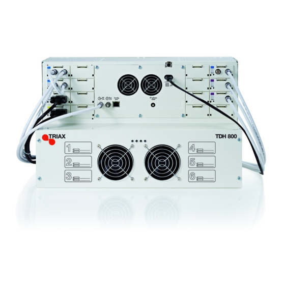
Headend overview Introduction The TDH800 headend accommodates up to 16 input modules and 6 quad output modules. 24 RF channels are accommodated. All incoming signals from input modules initially arrive in a ‘pool’, where they are converted to defined output signals, after which the converted signals are fed to output modules. -
Page 6: Components
Headend Overview Components Input slots (16 in total) Ventilation fans Earth terminal Power input RF output Distributes the RF channels from the output modules using an F-connector. Test point -20 dB RF test point of output (-20 dB). Configuration port Ethernet configuration port for setting up the headend unit. -
Page 7: Headend Installation
Headend Installation Headend installation Mounting You can mount the headend either onto a system rack or directly to a wall. Attach the mounting brackets to the headend with the supplied screws. Installation Bracket position Rack At the front of the headend. Wall At the rear of the headend. -
Page 8: Resetting The Ip Address
Headend installation Resetting the The IP address of a headend unit can be returned to the factory default address by using the IP address reset dial. IP address 1. Turn off the power. 2. Set the IP address reset dial to "7". 3. -
Page 9: Input Modules
Input modules Input modules You can install up to 16 input modules in the headend. Input module Each input module is identified through the use of a specifically types coloured label. The label also indicates the module type’s name and associated item number. -
Page 10: Attaching Cables
Input modules Attaching cables 1. Attach the signal cables to the ‘IN’ connector on the input module. Note: Ensure that enough cable is available for relocating input modules to alternate input slots at a later date. Looping cables Signals can be looped between DVB-S/S2 input modules: 1. -
Page 11: Input Module Status - Led
Input modules Input module Each input module has an LED on the front to indicate its current status - LED status when the headend is powered. Green - flashing The module is yet to be configured. Green No errors have been detected and the tuner is locked to the frequency. -
Page 12: Output Modules
Output modules Output You can install up to six output modules, each consisting of four RF channels. modules Output module Each output module is identified through use of a specifically coloured label. The label also indicates the module type’s name and associated types item number. -
Page 13: Removing Output Module
Output modules 2. Remove the bottom front cover by unscrewing the 4 screws indicated above. 3. Insert smart cards (if relevant). Insert the service provider’s smartcard into the CA module. Insert the CA module into either of the available slots in the output module. -
Page 14: System Monitoring
System monitoring System Monitoring LEDs Four LEDs are placed at the top of the output section of the headend unit, two of which provide information on the state of the headend. The LEDs are named (from left to right): System Status Tuner Status LED3 LED4... -
Page 15: Headend Configuration
Headend configuration Headend configuration The TDH800 headend needs to be configured before it can be used. System requirements Computer A computer meeting the following minimum requirements is necessary for configuring the headend. minimum requirements Operating system Windows XP or above Browser Windows Internet Explorer version 6.0 or equivalent... -
Page 16: Service Tool
Overview Service Tool 1. Open a web browser window. 2. Enter ‘http://192.168.0.100’ in the web address field. 3. Press Enter. 4. Enter the password. 5. Press the Log in button. Note: Password = ‘triax1234’ when the Service Tool is opened for the first time. -
Page 17: Overview
Overview Overview Communication icon Tabs Misc. buttons System icon Configuration buttons Communication Indicates whether the Service Tool is communicating correctly with the icons headend unit. Green The Service Tool and headend are communicating correctly. The Service Tool and headend are NOT communicating correctly. -
Page 18: Tabs
Overview Tabs You use the various tabs to configure the headend’s input and output modules. System The Service Tool’s ‘home’ window. Provides system overview information and configuration activation/ control. Input Tab for configuring input modules and services. Refer to input module manuals for information. Tab for configuring CI modules and CA cards. -
Page 19: Administration
General settings - administration Administration You must specify the system language, locale, and time zone for the headend unit. It is also necessary to specify IP addresses for headends which are located on a distribution network. Language 1. Press the Admin button at the top right-hand corner of the System window. -
Page 20: Location
General settings - administration Location 1. Press the Admin button at the top right-hand corner of the System window. 2. Expand the Country settings area. 3. Open the Current location drop-down list. 4. Select the country where the headend is located 5. -
Page 21: Security
General settings - administration 2. Expand the Time zone settings area. 3. Open the Input module (Main unit) drop-down list. 4. Select the input module that is to be used for setting the headend’s system date/time/time zone. 5. Press the OK button. Security 1. -
Page 22: Licences
1. Press the Admin button at the top right-hand corner of the System window. 2. Expand the Licence handling area. 3. Contact Triax Sales and provide the contents of the serial number and unique ID fields. 4. Enter the code provided by Triax Sales into the Activation key field. -
Page 23: Ip Addresses
General settings - administration IP addresses It may be necessary to specify specific IP addresses for the headend to avoid network IP address conflicts. Note: Headend IP addresses can be reset to factory default settings if required. This is done using the ID switch located on the headend unit. 1. -
Page 24: Rebooting
General settings - administration Rebooting 1. Expand the System maintenance area. 2. Press the Reboot button. Note: Changes to IP addresses only take effect when the headend has been rebooted. Viewing system It is possible to save log files for viewing headend actions. -
Page 25: Firmware
Windows operating system procedure. Firmware Updating Firmware updates are available from the Triax home page: www.Triax.com and then applied to the headend. Always read the release notes to determine whether the headend would benefit from available firmware updates or not. - Page 26 General settings - administration 3. Press the Upload file button. 4. Navigate to where the update file is saved. 5. Select the file. 6. Press the Open button. The new firmware update file is listed in the Change firmware dialog. 7.
- Page 27 General settings - administration 11. Press the Start update button. Note: The Update old packages radio button should only be used in cases where the headend consists mainly of new modules, but also contains some older modules that might benefit from an update. The firmware update takes approximately 5 minutes, during which time upgrade information is displayed in the Status area.
-
Page 28: Viewing System Information
General settings - administration Cleaning up Firmware to be deleted 1. Select the firmware updates to be removed from the system tool. 2. Press the Delete package button. Viewing system Detailed information about the headend unit is available in the System information window. - Page 29 Any headend system errors. Name and associated software version of input and output modules. Note that the software versions installed on the TDH 800 main unit and each input/output module must be identical. Update the software for the entire TDH 800 headend (including input/output modules) if this is not the case.
-
Page 30: Managing Configuration Files
Managing configuration files Managing configuration files Creating 1. Select the System tab. 2. Select the New button. An empty configuration file is created and listed in the configuration list area. Activating 1. Select the System tab. 2. Select the configuration that is to be actively used on the headend. 3. -
Page 31: Deleting
Managing configuration files Deleting 1. Select the System tab. 2. Highlight the configuration file to be deleted. 3. Press the Delete button. -
Page 32: Saving
Managing configuration files Saving Headend configuration files can, if desired, be saved on a computer. This simplifies the process of configuring additional headends. A saved configuration file can be used on headends that do not contain exactly the same modules. It will, however, be necessary to reconfigure/delete/add the modules that differ between the initial headend and the headend being configured. -
Page 33: Uploading
Managing configuration files 4. Navigate to where the configuration file is to be saved. 5. Enter a name for the configuration file. 6. Select ‘XML’ in the File type field. 7. Press the Save button. Uploading Configuration files previously saved on a computer can be transferred to the Service Tool to simplify the configuration process. -
Page 34: Network Tab Configuration
Note that Network ID’s and Network names are required for both DVB- T and DVB-C. Network ID Provided by the TDH 800 headend system. This cannot be modified. Network name Provided by the TDH 800 headend system. - Page 35 Configuring network Orig. network ID Enter an original network ID in the Orig. network ID field. This may be required by some set-top boxes. NIT Standard Default is ‘DVB’, ‘Nordig’ can also be selected. This field displays the EIT method being used and cannot be modified.
-
Page 36: Manufacturer
Triax Date: October 2012 Signature: triax.com/support Copyright © 2016 TRIAX. All rights reserved. The TRIAX Logo and TRIAX, TRIAX Multimedia 01-2014 Your ultimate connection are registered trademarks or trademarks of the TRIAX Company or its affiliates. All specifications in this guide are subject to change without further notice.
Need help?
Do you have a question about the TDH 800 and is the answer not in the manual?
Questions and answers