Flomec TM Series Owner's Manual
Hide thumbs
Also See for TM Series:
- Product owners manual (13 pages) ,
- Product owners manual (13 pages) ,
- Product owners manual (16 pages)
Table of Contents

Subscribe to Our Youtube Channel
Related Manuals for Flomec TM Series


Summary of Contents for Flomec TM Series
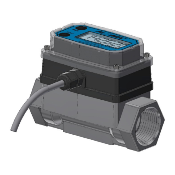
- Page 1 Product Owner’s Manual Module shown installed on G2 1” stainless steel flowmeter 4-20mA MODULE FOR USE WITH MOST* FLOMEC TURBINE METERS WITH Q9 DISPLAY *FLOMEC QSE meters have their own 4-20mA module 09/2021 920907-01 Rev. C...
- Page 2 Please save these instructions for future reference. Read carefully before attempting to assemble, install, operate or maintain the product described. Protect yourself and others by observing all safety information. Failure to comply with instructions could result in personal injury and/or property damage. Please refer to back cover for information regarding this product’s warranty and other important information.
-
Page 3: Table Of Contents
TABLE OF CONTENTS Getting Started ------------------------------------------------- 4 Electrical / Mechanical Specifications -------------------- 5 Approval Ratings ----------------------------------------------- 7 Installation ------------------------------------------------------- 8 Installing Module ------------------------------------------ 8 Wiring -------------------------------------------------------- 9 Operation / Calibration -------------------------------------- 11 Troubleshooting ---------------------------------------------- 12 Parts List ------------------------------------------------------- 15 Parts & Service ----------------------------------------------- 15 Warranty -------------------------------------------------------- 16... -
Page 4: Getting Started
• This 4-20mA module requires an input power of 8-32 volts DC (24 VDC is recommended). • This 4-20mA module is designed for use with most* FLOMEC meters that are equipped with the Q9 display option. The 4-20mA module can be field calibrated through the configuration menu options on the Q9 display. -
Page 5: Electrical / Mechanical Specifications
Ambient and Fluid Temperature Limits graph on next page Temperatures for higher process fluid temperature Limits. Obtainable with G2 If wider process fluid temperature ranges are desired, Stainless Steel Meters reference information on FLOMEC® Remote Kits. Storage temperature: -40° to +180°F (-40° to +82°C) Power: Type: Loop powered... - Page 6 SPECIFICATIONS (continued) AMBIENT AND FLUID TEMPERATURE LIMITS NOTE: The upper limit of the “Useable Combination” area can be increased by 10°F (6°C) when lithium batteries are installed in the Q9 Display.
-
Page 7: Approval Ratings
Module shown installed on G2 1” stainless steel flowmeter Figure 1 Note: This 4-20mA module is designed for use with most* FLOMEC meters that are equipped with the Q9 display option. The 4-20mA module can be field calibrated through the configuration menu options on the Q9 display. -
Page 8: Installation
INSTALLATION Installing Module NOTE: Factory installed 4-20mA modules will have the zero set to the meter’s minimum specified flow rate and the span will be set to the meter’s maximum specified flow rate. Remove the display electronics from the front of the turbine. NOTE: If you are installing more than one module at a time, take care to keep the proper electronics paired with the original turbine. -
Page 9: Wiring
INSTALLATION (Continued) Wiring The 4-20mA module comes pre-wired for external connections to external power and provides an open collector output, which can be set to either raw or scaled pulse output. The wires are color coded to connect as shown in Figures 3 & 4. Wire Color Feature 4-20mA (+) - Page 10 INSTALLATION (Continued) WIRING (Continued) NOTE: The internal and external options for the pull up resistance and voltage is selectable by the header on the 4-20mA board (see Figures 4a & 4b). When the Jumper is on the top two pins, the “external resistor required” option is selected (Figure 4a).
-
Page 11: Operation / Calibration
OPERATION / CALIBRATION Adjusting ZERO and SPAN To set or adjust ZERO and SPAN settings, refer to the Q9 Owner’s Manual (Non-Agency) Configuration Mode (Daughter Board Options) and Calibration Mode Section for further instructions. NOTE: The Q9 Display controls the 4-20 mA settings. It is recommended to verify and set (if necessary) the most optimal Calibration Method of the Q9 Display (see Q9 Owner’s Manual referenced above) before adjusting 4-20mA settings. -
Page 12: Troubleshooting
TROUBLESHOOTING Symptom Possible Cause(s) Corrective Action 1. Incorrect or no input power. 1. Supply correct power requirements. 2. Not wired correctly. 2. Check owner’s manual for correct installation. 3. Broken connection. 3. Check resistance to determine location of break. A. No output signal. 4. - Page 13 TROUBLE SHOOTING (Continued) 1. Q9 display showing velocity or 1. Press "top button" of Q9 volume totals instead of display until flowrate is flowrate. displayed (see Operation Section in Q9 owner's E. Q9 display value manual). not giving correct Flowrate. 2.
- Page 14 NOTES ________________________________________________________________________ ________________________________________________________________________ ________________________________________________________________________ ________________________________________________________________________ ________________________________________________________________________ ________________________________________________________________________ ________________________________________________________________________ ________________________________________________________________________ ________________________________________________________________________ ________________________________________________________________________ ________________________________________________________________________ ________________________________________________________________________ ________________________________________________________________________ ________________________________________________________________________ ________________________________________________________________________ ________________________________________________________________________ ________________________________________________________________________ ________________________________________________________________________ ________________________________________________________________________ ________________________________________________________________________ ________________________________________________________________________ ________________________________________________________________________ ________________________________________________________________________ ________________________________________________________________________...
-
Page 15: Parts List
PARTS LIST Part Number Description 901002-52 Seal PARTS & SERVICE For warranty consideration, parts, or other service information, please contact your local distributor. If you need further assistance, contact the GPI Product Support Department in Wichita, Kansas, during normal business hours. A toll free number is provided for your convenience. -
Page 16: Warranty
To make a claim against this warranty, or for technical assistance or repair, contact your FLOMEC distributor or contact FLOMEC at one of the locations below. In North or South America contact Outside North or South America contact Great Plains Industries, Inc.
Need help?
Do you have a question about the TM Series and is the answer not in the manual?
Questions and answers