Table of Contents
Advertisement
Quick Links
www.ti.com
User's Guide
TMDSCNCD28P65X controlCARD Information Guide
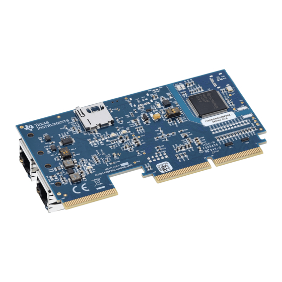
The F28P65x ControlCARD (TMDSCNCD28P65X) from Texas Instruments (TI) provides a great way to learn
and experiment with the F28P65x devices. The F28P65x device is a member of TI's C2000
microcontrollers (MCUs). This 180-pin controlCARD is intended to provide a well-filtered, robust design capable
of working in most environments. This document provides the hardware details of the F28P65x controlCARD
and explains the functions, locations of jumpers, and connectors present on the board.
1
Introduction.............................................................................................................................................................................2
2 Hardware Quick Setup Guide................................................................................................................................................
Standalone...............................................................................................................................................3
2.2 Configuration 2: External 5-V Supply.................................................................................................................................
3 Errata.......................................................................................................................................................................................
3.1 Warnings, Notes, and Errata..............................................................................................................................................
4 Getting Familiar with the controlCARD................................................................................................................................
4.1 F28P65X controlCARD Features.......................................................................................................................................
4.2 Assumed Operating Conditions.........................................................................................................................................
4.3 Using the controlCARD......................................................................................................................................................
4.4 Experimentation Software..................................................................................................................................................
5 Special Notes..........................................................................................................................................................................
5.1 XDS110 Emulator and SCI (UART) Connectivity...............................................................................................................
5.2 Evaluation of the Analog-to-Digital Converters (ADCs).....................................................................................................
6 Hardware References...........................................................................................................................................................
7 Revision History...................................................................................................................................................................
Figure 1-1. F28P65x controlCARD..............................................................................................................................................
Figure 4-1. Changing the Clock Source From 25 MHz to 20 MHz..............................................................................................
Figure 5-2. Female SMA Connector..........................................................................................................................................
Figure 6-2. Key Components on the controlCARD - Back.........................................................................................................
MCU114A....................................................................................................................................................................4
MCU114E2..................................................................................................................................................................4
MCU114E1..................................................................................................................................................................5
Table 4-1. Emulator Switch Selections........................................................................................................................................
Table 6-1. Hardware Connections.............................................................................................................................................
Table 6-2. LEDs.........................................................................................................................................................................
Capacitors..........................................................................................................................................12
Switches....................................................................................................................................................................12
Table 6-5. Test Points................................................................................................................................................................
Table 6-6. S3, Bootmode Selection...........................................................................................................................................
Trademarks
C2000
™
and Code Composer Studio
All trademarks are the property of their respective owners.
SPRUJ90A - MARCH 2023 - REVISED JULY 2023
Submit Document Feedback
ABSTRACT
Table of Contents
.............................................................................................................4
List of Figures
Circuitry...................................................................................................9
Front.........................................................................................................11
List of Tables
™
are trademarks of Texas Instruments.
Copyright © 2023 Texas Instruments Incorporated
™
family of
TMDSCNCD28P65X controlCARD Information Guide
Table of Contents
3
3
4
4
6
6
6
7
8
9
9
9
11
15
2
8
10
11
7
12
12
14
14
1
Advertisement
Table of Contents

Subscribe to Our Youtube Channel
Related Manuals for Texas Instruments TMDSCNCD28P65X


Summary of Contents for Texas Instruments TMDSCNCD28P65X
-
Page 1: Table Of Contents
Table of Contents User's Guide TMDSCNCD28P65X controlCARD Information Guide ABSTRACT The F28P65x ControlCARD (TMDSCNCD28P65X) from Texas Instruments (TI) provides a great way to learn ™ and experiment with the F28P65x devices. The F28P65x device is a member of TI’s C2000 family of microcontrollers (MCUs). -
Page 2: Introduction
Full compliance to safety, EMI/EMC, and other regulations are left to the designer of the customer’s system. TMDSCNCD28P65X controlCARD Information Guide SPRUJ90A – MARCH 2023 – REVISED JULY 2023 Submit Document Feedback Copyright © 2023 Texas Instruments Incorporated... -
Page 3: Hardware Quick Setup Guide
3. LEDs D1, D2, D6 and D7 on the controlCARD illuminate. 2.2 Configuration 2: External 5-V Supply 1. Insert the TMDSCNCD28P65X controlCARD into a TMDSHSECDOCK or other compatible docking station. 2. Connect a USB cable to J17 on the TMDSHSECDOCK. -
Page 4: Errata
5-V power supply instability can lead to device resets. The 5-V rail on the TMDSCNCD28P65X controlCARD can be powered from an on-board USB connector or from a baseboard like the TMDSHSECDOCK. A switch device on the controlCARD automatically selects the 5-V input power source for the controlCARD without the need for user configuration. -
Page 5: Table 3-3. Mcu114E1
Remove R80 and R81, then switch the traces using blue wire. Fix: None. 5-V power supply instability can lead to Section 3.1 about power supply instability. device resets SPRUJ90A – MARCH 2023 – REVISED JULY 2023 TMDSCNCD28P65X controlCARD Information Guide Submit Document Feedback Copyright © 2023 Texas Instruments Incorporated... -
Page 6: Getting Familiar With The Controlcard
TI recommends using an external power supply or power accessory that complies with applicable regional safety standards such as (by example) UL, CSA, VDE, CCC, PSE. TMDSCNCD28P65X controlCARD Information Guide SPRUJ90A – MARCH 2023 – REVISED JULY 2023 Submit Document Feedback Copyright © 2023 Texas Instruments Incorporated... -
Page 7: Using The Controlcard
More information on the controlCARD docking station can be found in the C2000Ware at the following location: <install directory>\c2000\C2000Ware_<rev>\boards\controlCARDs\TMDSCNCD28P65X\Rx_x. SPRUJ90A – MARCH 2023 – REVISED JULY 2023 TMDSCNCD28P65X controlCARD Information Guide Submit Document Feedback Copyright © 2023 Texas Instruments Incorporated... -
Page 8: Experimentation Software
C2000 series of MCUs. The CCS IDE is free to download and use with the controlCARD. Introductory videos for CCS IDE are available at training.ti.com. TMDSCNCD28P65X controlCARD Information Guide SPRUJ90A – MARCH 2023 – REVISED JULY 2023 Submit Document Feedback Copyright © 2023 Texas Instruments Incorporated... -
Page 9: Special Notes
Finally, TI recommends to use Negative-Positive 0 PPM/°C (NP0/C0G) capacitors as these have better stability over temperature and across input frequencies than other types of capacitors. SPRUJ90A – MARCH 2023 – REVISED JULY 2023 TMDSCNCD28P65X controlCARD Information Guide Submit Document Feedback Copyright © 2023 Texas Instruments Incorporated... -
Page 10: Figure 5-2. Female Sma Connector
30-Ω resistors and 300-pF capacitors were used. Using this setup, the ADC parameters were observed to be consistent with the numbers in the device-specific data sheet. Figure 5-2. Female SMA Connector TMDSCNCD28P65X controlCARD Information Guide SPRUJ90A – MARCH 2023 – REVISED JULY 2023 Submit Document Feedback Copyright © 2023 Texas Instruments Incorporated... -
Page 11: Hardware References
S3 – Boot Mode Switch D7 – 3.3-V Power good LED EVM Revision Figure 6-2. Key Components on the controlCARD - Back SPRUJ90A – MARCH 2023 – REVISED JULY 2023 TMDSCNCD28P65X controlCARD Information Guide Submit Document Feedback Copyright © 2023 Texas Instruments Incorporated... -
Page 12: Table 6-1. Hardware Connections
OFF – The C2000 MCU GPIO28 is NOT connected to the embedded XDS110. The corresponding pins on the 180-pin controlCARD connector can be used for another function. TMDSCNCD28P65X controlCARD Information Guide SPRUJ90A – MARCH 2023 – REVISED JULY 2023 Submit Document Feedback Copyright © 2023 Texas Instruments Incorporated... - Page 13 • RIGHT (default) position - External voltage reference is set to use an onboard precision 3.0 V voltage reference. SPRUJ90A – MARCH 2023 – REVISED JULY 2023 TMDSCNCD28P65X controlCARD Information Guide Submit Document Feedback Copyright © 2023 Texas Instruments Incorporated...
-
Page 14: Table 6-5. Test Points
0 (down, default) 1 (up, default) SCI / Wait Boot 1 (up) 0 (down) 1 (up) 1 (up) Flash / USB TMDSCNCD28P65X controlCARD Information Guide SPRUJ90A – MARCH 2023 – REVISED JULY 2023 Submit Document Feedback Copyright © 2023 Texas Instruments Incorporated... -
Page 15: Revision History
Updated S3, Bootmode Selection table......................11 • Updated item label formatting in Hardware Connections, LEDs, Resistors and Capacitors, Switches, Test Points tables ..............................SPRUJ90A – MARCH 2023 – REVISED JULY 2023 TMDSCNCD28P65X controlCARD Information Guide Submit Document Feedback Copyright © 2023 Texas Instruments Incorporated... - Page 16 STANDARD TERMS FOR EVALUATION MODULES Delivery: TI delivers TI evaluation boards, kits, or modules, including any accompanying demonstration software, components, and/or documentation which may be provided together or separately (collectively, an “EVM” or “EVMs”) to the User (“User”) in accordance with the terms set forth herein.
- Page 17 www.ti.com Regulatory Notices: 3.1 United States 3.1.1 Notice applicable to EVMs not FCC-Approved: FCC NOTICE: This kit is designed to allow product developers to evaluate electronic components, circuitry, or software associated with the kit to determine whether to incorporate such items in a finished product and software developers to write software applications for use with the end product.
- Page 18 www.ti.com Concernant les EVMs avec antennes détachables Conformément à la réglementation d'Industrie Canada, le présent émetteur radio peut fonctionner avec une antenne d'un type et d'un gain maximal (ou inférieur) approuvé pour l'émetteur par Industrie Canada. Dans le but de réduire les risques de brouillage radioélectrique à...
- Page 19 www.ti.com EVM Use Restrictions and Warnings: 4.1 EVMS ARE NOT FOR USE IN FUNCTIONAL SAFETY AND/OR SAFETY CRITICAL EVALUATIONS, INCLUDING BUT NOT LIMITED TO EVALUATIONS OF LIFE SUPPORT APPLICATIONS. 4.2 User must read and apply the user guide and other available documentation provided by TI regarding the EVM prior to handling or using the EVM, including without limitation any warning or restriction notices.
- Page 20 Notwithstanding the foregoing, any judgment may be enforced in any United States or foreign court, and TI may seek injunctive relief in any United States or foreign court. Mailing Address: Texas Instruments, Post Office Box 655303, Dallas, Texas 75265 Copyright © 2023, Texas Instruments Incorporated...
- Page 21 TI products. TI’s provision of these resources does not expand or otherwise alter TI’s applicable warranties or warranty disclaimers for TI products. TI objects to and rejects any additional or different terms you may have proposed. IMPORTANT NOTICE Mailing Address: Texas Instruments, Post Office Box 655303, Dallas, Texas 75265 Copyright © 2023, Texas Instruments Incorporated...
Need help?
Do you have a question about the TMDSCNCD28P65X and is the answer not in the manual?
Questions and answers