
Related Manuals for Huawei ATN 950B


Summary of Contents for Huawei ATN 950B
- Page 1 ATN 950B Multi-service Access Equipment V200R001C02 Hardware Description Issue Date 2012-07-23 HUAWEI TECHNOLOGIES CO., LTD.
- Page 2 All other trademarks and trade names mentioned in this document are the property of their respective holders. Notice The purchased products, services and features are stipulated by the contract made between Huawei and the customer. All or part of the products, services and features described in this document may not be within the purchase scope or the usage scope.
-
Page 3: About This Document
ATN 950B Multi-service Access Equipment Hardware Description About This Document About This Document Related Version The following table lists the product version related to this document. Product Name Version ATN 950B V200R001C02 Intended Audience This document describes the equipment structure, chassis structure, and board classification. - Page 4 ATN 950B Multi-service Access Equipment Hardware Description About This Document Symbol Description Indicates a tip that may help you solve a problem or save time. Provides additional information to emphasize or supplement NOTE important points of the main text. Command Conventions...
- Page 5 ATN 950B Multi-service Access Equipment Hardware Description About This Document Changes in Issue 03 (2012-07-23) This document has the following updates: The known bugs are fixed. Changes in Issue 02 (2012-06-30) This document has the following updates: The known bugs are fixed.
-
Page 6: Table Of Contents
ATN 950B Multi-service Access Equipment Hardware Description Contents Contents About This Document........................ii 1 Overview............................1 1.1 Appearance of the Device...........................2 1.2 Slot Allocation..............................2 1.3 Boards and Valid Slots............................3 1.4 System Architecture............................4 1.5 Technical Specifications.............................5 2 Power Supply System........................9 2.1 Power Supply System Structure........................10 2.2 PIU - Power Interface Board..........................11... - Page 7 ATN 950B Multi-service Access Equipment Hardware Description Contents 4.4 Front Panel................................29 4.5 CF Card and DIP Switch..........................33 4.6 Technical Specifications...........................34 5 Physical Interface Card.......................35 5.1 AND1EM4T - 4 Channels GE/FE Electrical Interface Board .................36 5.1.1 Overview..............................36 5.1.2 Functions and Features..........................36 5.1.3 Working Principle and Signal Flow......................36...
- Page 8 ATN 950B Multi-service Access Equipment Hardware Description Contents 5.7.2 Functions and Features..........................68 5.7.3 Working Principle and Signal Flow......................69 5.7.4 Front Panel...............................71 5.7.5 Technical Specifications..........................73 5.8 AND2MD1A/AND2MD1B - 32 Channels E1 Interface Board...............74 5.8.1 Overview..............................74 5.8.2 Functions and Features..........................74 5.8.3 Working Principle and Signal Flow......................76 5.8.4 Front Panel...............................78...
- Page 9 ATN 950B Multi-service Access Equipment Hardware Description Contents 13.3 Technical Specifications of the 10 GE Interfaces..................125 13.4 Technical Specifications of E1 Electrical Interfaces..................125 Issue 03 (2012-07-23) Huawei Proprietary and Confidential viii Copyright © Huawei Technologies Co., Ltd.
-
Page 10: Overview
Boards are the key hardware components of the equipment. This section describes the boards supported by the ATN 950B and their valid slots. 1.4 System Architecture Boards for the ATN 950B are used together to provide various functions for the equipment. 1.5 Technical Specifications Issue 03 (2012-07-23) Huawei Proprietary and Confidential Copyright ©... -
Page 11: Appearance Of The Device
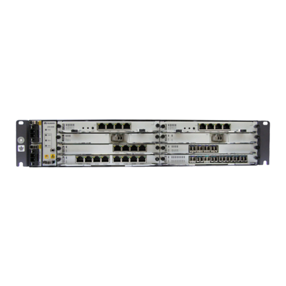
ATN 950B. Figure 1-1 Appearance of the ATN 950B The dimensions of the ATN 950B are 442 mm (width) x 220 mm (depth) x 2 U (height, 1 U = 44.45 mm). The ATN 950B can be installed in the following: ETSI cabinet (300 mm[11.81 in.] deep) -
Page 12: Boards And Valid Slots
Boards are the key hardware components of the equipment. This section describes the boards supported by the ATN 950B and their valid slots. Table 1-1 shows the boards supported by the ATN 950B and their valid slots. Table 1-1 Boards supported by the ATN 950B and their valid slots Board Name... -
Page 13: System Architecture
To facilitate cabling deployment, do not insert the E1 board and the EM8T, EM8F, EM4T, or EM4F board to the two slots at the same layer. 1.4 System Architecture Boards for the ATN 950B are used together to provide various functions for the equipment. Figure 1-3 shows board relations of the ATN 950B. -
Page 14: Technical Specifications
ATN 950B Multi-service Access Equipment Hardware Description 1 Overview Figure 1-3 Board relations of the ATN 950B 1. NM interface/ Console interface 2. Clock input/output interface 3. Time input/output interface 4. Alarm input/output interface User side Network side Control and management... - Page 15 ATN 950B Multi-service Access Equipment Hardware Description 1 Overview Technical Description Specifications Weight Empty chassis: 2.80 kg (6.17 lb) Environment Requirements Item Description Storage -40 °C to +70 °C (-40°F to 158°F) temperature Storage 10% to 100% relative humidity Storage Lower than 4000 m (13123.2 ft)
- Page 16 ATN 950B Multi-service Access Equipment Hardware Description 1 Overview Power Consumption, Heat Consumption, and Power Supply Requirements Table 1-4 Technical specifications of the chassis Technical Description Specifications Power consumption and l Typical configuration I (with system protection) heat consumption (with Power consumption: 141.17 W...
- Page 17 ATN 950B Multi-service Access Equipment Hardware Description 1 Overview Reliability Specifications Item Description MTBF 199998 hours MTTR 2 hours System usability 0.99999 System Configurations Item Description Total number of slots Number of system control board slots Number of service sub-board slots...
-
Page 18: Power Supply System
The TND1PIU inputs -48 V DC power to the ATN 950B, or an EPS30-4815AF external AC power supply system inputs 220 V AC power, and converts the AC power to the DC power, and then outputs the DC power to the ATN 950B. Both DC and AC power supplies support 1+1 hot backup. -
Page 19: Power Supply System Structure
2 Power Supply System 2.1 Power Supply System Structure When DC power supplies are directly input to the ATN 950B, the two PIU boards form 1+1 hot backups. When the EPS30-4815AF external AC power supply system provides power supplies to the ATN 950B, it converts two AC power supplies into two DC power supplies, and outputs the two DC power supplies to the two PIU boards. -
Page 20: Piu - Power Interface Board
ATN 950B Multi-service Access Equipment Hardware Description 2 Power Supply System 2.2 PIU - Power Interface Board This section describes the TND1PIU, a power interface board, in terms of the overview, functions, features, working principle, front panel, and technical specifications. -
Page 21: Front Panel
ATN 950B Multi-service Access Equipment Hardware Description 2 Power Supply System Figure 2-3 Block diagram for the working principle of the PIU Backplane -48 V/-60 V Communication unit Each board module Surge protection failure alarm signals Inter-board communication bus Surge protection and failure... - Page 22 ATN 950B Multi-service Access Equipment Hardware Description 2 Power Supply System Figure 2-4 Appearance of the front panel of the PIU Indicators The following indicator is present on the front panel of the PIU. PWR, green, which indicates the power supply status. When PWR is on and green, it indicates that power is accessed.
-
Page 23: Technical Specifications
The EPS30-4815AF external power supply system inputs 220 V AC power and converts the power to -53.5 V DC required by the ATN 950B. When input of the 220 V AC power stops, the EPS30-4815AF automatically switches to the storage battery, which provides power to the equipment. - Page 24 ATN 950B Multi-service Access Equipment Hardware Description 2 Power Supply System Figure 2-5 Appearance of the EPS30-4815AF CAUTION The interface on the monitoring module is reserved. Do not use the interface on the monitoring module; otherwise, the EPS30-4815AF will be reset or damaged.
- Page 25 Provides one interface for connecting to a group of storage batteries. When working normally, the EPS30-4815AF is charging the storage batteries. When input of the 220 V AC power stops, the storage batteries provide power to the ATN 950B. This ensures uninterrupted power supply to the ATN 950B.
-
Page 26: Front Panel
ATN 950B Multi-service Access Equipment Hardware Description 2 Power Supply System 2.3.2 Front Panel On the front panel of the EPS30-4815AF, there are indicators, interfaces, and output branch fuses. Appearance of the Front Panel Figure 2-8 shows the appearance of the front panel of the EPS30-4815AF. - Page 27 LOAD1 and LOAD2 provide DC power for two PIUs. For how to LOAD2 Output interface for load 2 connect the load interfaces to the PIUs, see the ATN 950B Installation Guide. Issue 03 (2012-07-23) Huawei Proprietary and Confidential Copyright © Huawei Technologies Co., Ltd.
- Page 28 ATN 950B Multi-service Access Equipment Hardware Description 2 Power Supply System Interface Numb Interface Description Remarks Name er of Type Interfa The pins marked with + and - are BATT Interface for connecting to the connected to the 48V+ and 48V-...
-
Page 29: Technical Specifications
ATN 950B Multi-service Access Equipment Hardware Description 2 Power Supply System CAUTION Do not change the default setting of the DIP switch. Otherwise, the EPS30-4815AF is affected. The DIP switch indicates eight bits in binary format (on: 1; off: 0). The default value of the eight bits is 00000100. -
Page 30: Heat Dissipation System
3.1 System Air Channel ATN 950B dissipates heat by blowing air in a left-to-right direction. 3.2 FAN - Fan Board This section describes the AND1FAN, a fan board, in terms of the overview, functions, features, working principle, front panel, and technical specifications. -
Page 31: System Air Channel
ATN 950B Multi-service Access Equipment Hardware Description 3 Heat Dissipation System 3.1 System Air Channel ATN 950B dissipates heat by blowing air in a left-to-right direction. Figure 3-1 shows the system air channel. Figure 3-1 Air flow in the ATN 950B 3.2 FAN - Fan Board... - Page 32 ATN 950B Multi-service Access Equipment Hardware Description 3 Heat Dissipation System Figure 3-2 Block diagram for the working principle of the AND1FAN Fans x 6 12 V 12 V 12 V Start-delay Combiner Filter module Combiner/ 12 V 12 V...
-
Page 33: Front Panel
ATN 950B Multi-service Access Equipment Hardware Description 3 Heat Dissipation System 3.2.4 Front Panel On the front panel of the FAN, there are indicators, ESD wrist strap jack, handle, and labels. Appearance of the Front Panel Figure 3-3 shows the appearance of the front panel of the FAN. -
Page 34: Technical Specifications
ATN 950B Multi-service Access Equipment Hardware Description 3 Heat Dissipation System Label The following labels are present on the front panel of the FAN: ESD protection label, which indicates that the equipment is static-sensitive. Fan warning label, which says that do not touch the fan leaves before the fan stops rotating. -
Page 35: And1Cxpa/And1Cxpb - System Control, Cross-Connect, And Multi-Protocol Process Unit
ATN 950B Multi-service Access Equipment 4 AND1CXPA/AND1CXPB - System Control, Cross- Hardware Description connect, and Multi-protocol Process Unit AND1CXPA/AND1CXPB - System Control, Cross-connect, and Multi-protocol Process Unit About This Chapter This section describes AND1CXPA/AND1CXPB, which is the system control, cross-connect and protocol processing board, in terms of the overview, functions, features, working principle, front panel, and technical specifications. -
Page 36: Overview
ATN 950B Multi-service Access Equipment 4 AND1CXPA/AND1CXPB - System Control, Cross- Hardware Description connect, and Multi-protocol Process Unit 4.1 Overview The AND1CXPA/AND1CXPB (CXPA/CXPB for short) is a control, cross-connect, and protocol processing board. The function version of the CXPA/CXPB is AND1. The CXPA/ CXPB is housed in slot 7 or slot 8. -
Page 37: Working Principle And Signal Flow
ATN 950B Multi-service Access Equipment 4 AND1CXPA/AND1CXPB - System Control, Cross- Hardware Description connect, and Multi-protocol Process Unit Function and Feature Description Tact switches Provides two tact switches. When you rotate the ejector levers to remove the board, the two tact switches are triggered to start the active/standby protection switching. -
Page 38: Front Panel
ATN 950B Multi-service Access Equipment 4 AND1CXPA/AND1CXPB - System Control, Cross- Hardware Description connect, and Multi-protocol Process Unit Grooms services with switching capacity. Supports automatic switching and manual switching of the active and standby boards. System Control Module This module mainly consists of the CPU control unit and logic control unit, which perform the... - Page 39 ATN 950B Multi-service Access Equipment 4 AND1CXPA/AND1CXPB - System Control, Cross- Hardware Description connect, and Multi-protocol Process Unit Appearance of the Front Panel Figure 4-2 shows the appearance of the front panel of the AND1CXPB. Figure 4-2 Front panel of the AND1CXPB...
- Page 40 ATN 950B Multi-service Access Equipment 4 AND1CXPA/AND1CXPB - System Control, Cross- Hardware Description connect, and Multi-protocol Process Unit Table 4-2 Types and usage of the interfaces on the AND1CXPB Interface Interface Usage Correspondi on the Type ng Cable Front Panel...
- Page 41 ATN 950B Multi-service Access Equipment 4 AND1CXPA/AND1CXPB - System Control, Cross- Hardware Description connect, and Multi-protocol Process Unit Front View Usage Positive transmit end of external clock Unspecified Unspecified Unspecified Table 4-5 Pins of the TOD interface Front View Working Mode...
-
Page 42: Cf Card And Dip Switch
ATN 950B Multi-service Access Equipment 4 AND1CXPA/AND1CXPB - System Control, Cross- Hardware Description connect, and Multi-protocol Process Unit Table 4-6 Pins of the ALMI/O interface Front View Usage Input for the digital parameter Grounding end Input for the digital parameter... -
Page 43: Technical Specifications
ATN 950B Multi-service Access Equipment 4 AND1CXPA/AND1CXPB - System Control, Cross- Hardware Description connect, and Multi-protocol Process Unit CF Card The size of the CF card on AND1CXPA/AND1CXPB is 512 MB. The CF card is used to backup data and load packages. -
Page 44: Physical Interface Card
Physical Interface Card About This Chapter This topic describes the PIC cards that can be used by the ATN 950B. 5.1 AND1EM4T - 4 Channels GE/FE Electrical Interface Board This section describes the AND1EM4T (a 4 channels GE/FE electrical interface board), in terms of version, function, principle, front panel, and technical specifications. -
Page 45: And1Em4T - 4 Channels Ge/Fe Electrical Interface Board
ATN 950B Multi-service Access Equipment Hardware Description 5 Physical Interface Card 5.1 AND1EM4T - 4 Channels GE/FE Electrical Interface Board This section describes the AND1EM4T (a 4 channels GE/FE electrical interface board), in terms of version, function, principle, front panel, and technical specifications. - Page 46 ATN 950B Multi-service Access Equipment Hardware Description 5 Physical Interface Card Figure 5-1 Block diagram for the functions of the AND1EM4T Back plane 4 x FE/GE Service Service signals Service signals electrical signals Service access processing module module Management bus...
-
Page 47: Front Panel
ATN 950B Multi-service Access Equipment Hardware Description 5 Physical Interface Card In the receive direction, this module receives and buffers the service packets from the interface conversion module. Then, this module schedules packets from different interfaces. Finally, this module outputs the packets through the backplane-side interface. -
Page 48: Technical Specifications
ATN 950B Multi-service Access Equipment Hardware Description 5 Physical Interface Card STAT indicator, red, green, or orange, which indicates the working status LINK indicator, green, which indicates the connection status of the port ACT indicator, yellow, which indicates the data transceiving status of the port NOTE .Above each service interface, there is a service port connection status indicator (LINK) and a service port... -
Page 49: And1Em8T - 8 Channels Ge/Fe Electric Interface Board
ATN 950B Multi-service Access Equipment Hardware Description 5 Physical Interface Card Interface Specifications Table 5-4 lists the specifications of the electrical interfaces on the AND1EM4T board. Table 5-4 Technical specifications of the FE/GE electrical interface Item Specification Electrical signal interface rate Supports interface rates at 100 Mbit/s and 1000 Mbit/s. -
Page 50: Working Principle And Signal Flow
ATN 950B Multi-service Access Equipment Hardware Description 5 Physical Interface Card Function and Feature Description Interface function Supports PHY-layer inloop. Supports MAC-layer outloop. Supports automatic loopback release at the port. Clock Supports synchronous Ethernet. Supports SSM protocol. Supports IEEE 1588V2 protocol. - Page 51 ATN 950B Multi-service Access Equipment Hardware Description 5 Physical Interface Card the services to the service processing module. The service processing module buffers the service packets, schedules the packets, and finally outputs the packets through the backplane-side interface. Service Access Module...
-
Page 52: Front Panel
ATN 950B Multi-service Access Equipment Hardware Description 5 Physical Interface Card 1.2 V 5.2.4 Front Panel On the front panel of the AND1EM8T, there are indicators and interfaces. Appearance of the Front Panel Figure 5-4 shows the appearance of the front panel of the AND1EM8T. -
Page 53: Technical Specifications
ATN 950B Multi-service Access Equipment Hardware Description 5 Physical Interface Card Table 5-7 Pins of the FE/GE electrical interfaces Front View Usage Positive of twisted pair 1 Negative of twisted pair 1 Positive of twisted pair 2 Positive of twisted pair 3... -
Page 54: Overview
ATN 950B Multi-service Access Equipment Hardware Description 5 Physical Interface Card 5.3.1 Overview The AND1EM4F (EM4F for short) is a four channels FE/GE optical interface board. The function version of the EM4F is AND1. The AND1EM4F is housed in any of slots 1 to 4. - Page 55 ATN 950B Multi-service Access Equipment Hardware Description 5 Physical Interface Card Figure 5-5 Block diagram for the functions of the AND1EM4F Back plane 4 x FE/GE Service Service signals Service signals optical signals Service access processing module module Management bus...
-
Page 56: Front Panel
ATN 950B Multi-service Access Equipment Hardware Description 5 Physical Interface Card In the receive direction, this module receives and buffers the service packets from the service access module. Then, this module schedules packets from different interfaces. Finally, this module outputs the packets through the backplane-side interface. -
Page 57: Technical Specifications
ATN 950B Multi-service Access Equipment Hardware Description 5 Physical Interface Card STAT indicator, red, green, or orange, which indicates the working status L/A0 to L/A3 indicators, green or orange, which indicate the port connection status and data transmit/receive status For details on meanings of indicators, see Indicators. - Page 58 ATN 950B Multi-service Access Equipment Hardware Description 5 Physical Interface Card Table 5-11 Technical specifications of the GE optical interface Item Specification Optical Two-fiber bidirectional interface Single-fiber bidirectional interface interface 1000BAS 1000BAS 1000BAS 1000BAS 1000BAS 1000BAS 1000BAS 1000BAS type E-SX...
-
Page 59: And1Em8F - 8 Channels Ge/Fe Optical Interface Board
ATN 950B Multi-service Access Equipment Hardware Description 5 Physical Interface Card Item Specification Working wavelength 1261 to 1360 1263 to 1360 1480 to 1580 range (nm) Mean launched -15 to -8 -5 to 0 -5 to 0 optical power (dBm) -
Page 60: Working Principle And Signal Flow
ATN 950B Multi-service Access Equipment Hardware Description 5 Physical Interface Card Table 5-13 Functions and features of the AND1EM8F Function and Feature Description Basic function Supports eight FE/GE optical interfaces, on which FE optical modules and GE optical modules can be mixedly used. - Page 61 ATN 950B Multi-service Access Equipment Hardware Description 5 Physical Interface Card destination interfaces for the packets, and buffers and schedules the packets. Then, the service processing module sends the processed packets to the service access module, where coding/ decoding, serial/parallel conversion, and E/O conversion are performed. Finally, the service access module outputs the packets through the GE/FE interfaces on the front panel.
-
Page 62: Front Panel
ATN 950B Multi-service Access Equipment Hardware Description 5 Physical Interface Card Power Supply Module This module provides the DC power of the following specifications to each module on the EM8F. 3.3 V 3.0 V 2.5 V 1.8 V 1.2 V 5.4.4 Front Panel... -
Page 63: Technical Specifications
ATN 950B Multi-service Access Equipment Hardware Description 5 Physical Interface Card Table 5-14 Types and usage of the interfaces on the AND1EM8F Interface on the Front Interface Usage Correspo Panel Type nding Cable Fiber Optical IN0 to IN7 When a two-fiber bidirectional... - Page 64 ATN 950B Multi-service Access Equipment Hardware Description 5 Physical Interface Card Item Specification Working 770 to 1270 to 1260 to 1500 to Tx: 1260 Tx: 1480 Tx: 1260 Tx: 1480 waveleng 1360 1360 1580 to 1360 to 1500 to 1360...
-
Page 65: And1Ex1 - 1 Channel 10 Ge Optical Interface Board
ATN 950B Multi-service Access Equipment Hardware Description 5 Physical Interface Card Item Specification Minimum extinction ratio (dB) Optical module code S4015755 S4015715 34060282 NOTE For details of the optical module, see 7.2 Optical Module Labels. Physical Specifications Board dimensions (mm): 22.86 (H) x 225.75 (D) x 193.80 (W) Weight (kg): 0.46... -
Page 66: Working Principle And Signal Flow
ATN 950B Multi-service Access Equipment Hardware Description 5 Physical Interface Card Function and Feature Description Supports automatic loopback release at the port. Clock Supports synchronous Ethernet. Supports SSM protocol. Supports IEEE 1588V2 protocol. Supports 1588 ACR clock. 5.5.3 Working Principle and Signal Flow... - Page 67 ATN 950B Multi-service Access Equipment Hardware Description 5 Physical Interface Card schedules the service packets, and finally outputs the packets through the backplane-side interface. Service Access Module This module performs the following functions: In the receive direction, this module receives the 10 GE services from the interfaces on the front panel, performs serial/parallel conversion, and coding/decoding, and then sends the services to the service processing module.
-
Page 68: Front Panel
ATN 950B Multi-service Access Equipment Hardware Description 5 Physical Interface Card 5.5.4 Front Panel On the front panel of the AND1EX1, there are indicators and an interface. Appearance of the Front Panel Figure 5-10 shows the appearance of the front panel of the AND1EX1. -
Page 69: And1Ml1/And1Ml1A - 16 Channels E1 Electrical Interface Board
ATN 950B Multi-service Access Equipment Hardware Description 5 Physical Interface Card Table 5-19 Technical specifications of the 10GE optical interface Item Specification Optical interface type Two-fiber bidirectional interface 10GE 10GE 10GE (10 km) (40 km) (80 km) Fiber type Single-mode... -
Page 70: Functions And Features
ATN 950B Multi-service Access Equipment Hardware Description 5 Physical Interface Card The ML1A has two function versions, that is, AND1 and AND2. Table 5-20 lists the differences between these two versions. Table 5-20 Differences between the two function versions of the ML1... - Page 71 ATN 950B Multi-service Access Equipment Hardware Description 5 Physical Interface Card Function and Feature Remarks Maximum number of E1 links in each IMA group Dynamically enables or disables the IMA group, restarts the IMA group protocol, and dynamically adds or deletes the IMA group members.
-
Page 72: Working Principle And Signal Flow
ATN 950B Multi-service Access Equipment Hardware Description 5 Physical Interface Card Function and Feature Remarks ML-PPP Number of supported ML- PPP groups Maximum number of links supported by each ML-PPP group Functions as the UNI interface to access IP packets of the L3VPN services. -
Page 73: Front Panel
ATN 950B Multi-service Access Equipment Hardware Description 5 Physical Interface Card module decapsulates the concatenated services and buffers the services in queues. Then, this module schedules the egress queues according to the service types, processes and converts the services, and finally sends the services to the line-side processing module. The line-side processing module performs coding, dejitter, pulse shaping, and line driving for the services, and finally sends the services to E1 interfaces. - Page 74 ATN 950B Multi-service Access Equipment Hardware Description 5 Physical Interface Card Figure 5-12 Front panel of the AND1ML1 Figure 5-13 shows the appearance of the front panel of the AND1ML1A. Figure 5-13 Front panel of the AND1ML1A Indicators The following indicators are present on the front panel of the AND1ML1/AND1ML1A:...
- Page 75 ATN 950B Multi-service Access Equipment Hardware Description 5 Physical Interface Card Table 5-23 Pins of the Anea 96 interface Front View Connector Pin Usage Connector Pin Usage R x 1 T x 1 R x 2 T x 2 R x 3...
-
Page 76: Specifications
ATN 950B Multi-service Access Equipment Hardware Description 5 Physical Interface Card Front View Connector Pin Usage Connector Pin Usage R x 16 T x 16 5.6.5 Specifications The technical specifications of the AND1ML1/AND1ML1A include the interface specifications, dimensions, weight, and power consumption. -
Page 77: And3Ml1A/And3Ml1B - 16 Channels E1 Interface Board
ATN 950B Multi-service Access Equipment Hardware Description 5 Physical Interface Card 5.7 AND3ML1A/AND3ML1B - 16 Channels E1 Interface Board This section describes the AND3ML1A/AND3ML1B, a 16 channels E1 electrical interface board, in terms of the overview, functions, features, working principle, front panel, and technical specifications. -
Page 78: Working Principle And Signal Flow
ATN 950B Multi-service Access Equipment Hardware Description 5 Physical Interface Card Function and Feature Remarks Supported traffic types l CBR l UBR l UBR+ l rt-VBR l nrt-VBR Number of supported ATM 256 remote connections connections 128 local connections (VPC and VCC included) - Page 79 ATN 950B Multi-service Access Equipment Hardware Description 5 Physical Interface Card Figure 5-14 shows the functional block diagram of the AND3ML1A/AND3ML1B. Figure 5-14 Functional block diagram of the AND3ML1A/AND3ML1B Backplane 16 x E1 Service signal Service Service signal Service access...
-
Page 80: Front Panel
ATN 950B Multi-service Access Equipment Hardware Description 5 Physical Interface Card This module recovers the line clock. Service Processing Module This module performs the following functions: In the receive direction, this module receives the signals from the service access module and performs E1 framing. - Page 81 ATN 950B Multi-service Access Equipment Hardware Description 5 Physical Interface Card Indicators The following indicators are present on the front panel of the AND3ML1A/AND3ML1B: STAT indicator, red, green, or orange, which indicates the working status For details on meanings of indicators, see Indicators.
-
Page 82: Technical Specifications
ATN 950B Multi-service Access Equipment Hardware Description 5 Physical Interface Card Front View Connector Pin Usage Connector Pin Usage R x 6 T x 6 R x 7 T x 7 R x 8 T x 8 R x 9... -
Page 83: And2Md1A/And2Md1B - 32 Channels E1 Interface Board
ATN 950B Multi-service Access Equipment Hardware Description 5 Physical Interface Card Table 5-28 Specifications of the interfaces on the AND3ML1A/AND3ML1B Item Specification Requirement Nominal bit rate (kbit/s) 2048 Interface impedance 75 ohms (ML1A) 120 ohms (ML1B) Interface code HDB3 Pulse waveform at the output interface Complies with ITU-T G.703... - Page 84 ATN 950B Multi-service Access Equipment Hardware Description 5 Physical Interface Card at interfaces on the AND2MD1A/AND2MD1B can be flexibly configured, and protocols such as ATM TC, IMA, CES, and ML-PPP are supported. Table 5-29 lists the functions and features of the AND2MD1A/AND2MD1B.
-
Page 85: Working Principle And Signal Flow
ATN 950B Multi-service Access Equipment Hardware Description 5 Physical Interface Card Function and Feature Remarks Supports the timeslot compression function. Provides the vacant 64 kbit/s timeslot suppression function for the CES services in the CESoPSN mode to save the transmission bandwidth. - Page 86 ATN 950B Multi-service Access Equipment Hardware Description 5 Physical Interface Card Transmit Direction The service signals from the AND1CXPA/AND1CXPB are sent to the service processing module. The service processing module performs PWE3 decapsulation and PW scheduling for the service signals, processes the service signals based on the IMA/ATM, CES, and ML-PPP protocols, performs the E1 framing function, and sends the service signals to the service access module.
-
Page 87: Front Panel
ATN 950B Multi-service Access Equipment Hardware Description 5 Physical Interface Card Clock Module This module performs the following functions: When used with the AND1CXPA/AND1CXPB, processes the recovered line clock. Provides the working clock for each module on the board. Power Supply Module This module converts the input DC voltage into various DC voltages required by each module on the board. - Page 88 ATN 950B Multi-service Access Equipment Hardware Description 5 Physical Interface Card Table 5-30 Type and usage of the interfaces on the front panel of the AND2MD1A/AND2MD1B Interfac Interfac Usage e on the e Type AND2MD1A AND2MD1B Front Panel 0 to 15...
-
Page 89: Technical Specifications
ATN 950B Multi-service Access Equipment Hardware Description 5 Physical Interface Card Front View Connector Pin Usage Connector Pin Usage R x 9 T x 9 R x 10 T x 10 R x 11 T x 11 R x 12... - Page 90 ATN 950B Multi-service Access Equipment Hardware Description 5 Physical Interface Card Item Specification Requirement Attenuation tolerance of the input 0 to 6 interface at the point with a frequency of 1024 kHz (dB) Anti-interference capability of the Complies with ITU-T G.703...
-
Page 91: Filler Panel
ATN 950B Multi-service Access Equipment Hardware Description 6 Filler Panel Filler Panel About This Chapter A filler panel is used to cover any vacant slot in a chassis. 6.1 Functions and Features A filler panel can be used to perform electromagnetic shielding, keep out foreign substances, and ensure proper ventilation. -
Page 92: Functions And Features
ATN 950B Multi-service Access Equipment Hardware Description 6 Filler Panel 6.1 Functions and Features A filler panel can be used to perform electromagnetic shielding, keep out foreign substances, and ensure proper ventilation. Main functions of a filler panel are as follows: Performs electromagnetic shielding and ensures that the chassis meets the requirement of electromagnetic radiation. -
Page 93: Pluggable Optical Modules
7 Pluggable Optical Modules Pluggable Optical Modules About This Chapter Optical interface boards for the ATN 950B use the enhanced small form-factor pluggable (eSFP) optical module. The eSFP optical module, which is a protocol-independent optical transceiver applicable to optical communication, implements O/E and E/O conversion for signals, and supports query of information such as the transceiver performance and manufacturer. -
Page 94: Appearance And Application
ATN 950B Multi-service Access Equipment Hardware Description 7 Pluggable Optical Modules 7.1 Appearance and Application The eSFP optical module can be inserted in GE and FE optical interfaces. Appearance Figure 7-1 shows the appearance of the eSFP optical module. Figure 7-1 Appearance of the eSFP optical module... - Page 95 ATN 950B Multi-service Access Equipment Hardware Description 7 Pluggable Optical Modules As shown in Table 7-2, different types of optical modules have different part numbers. Table 7-2 Part numbers and types of optical modules Optical Optical Optical Module Information Mapping...
- Page 96 ATN 950B Multi-service Access Equipment Hardware Description 7 Pluggable Optical Modules S4015794 10GBASE-ZR Optical Transceiver, eSFP, 1550 nm, 9.95 Gbit/s to 11.1 Gbit/s, LC, Single- (80 km) mode, 80 km Issue 03 (2012-07-23) Huawei Proprietary and Confidential Copyright © Huawei Technologies Co., Ltd.
-
Page 97: Pluggable Electrical Module
ATN 950B Multi-service Access Equipment Hardware Description 8 Pluggable Electrical Module Pluggable Electrical Module A pluggable electrical module is used at a GE SFP interface to transmit/receive GE electrical signals. Appearance Figure 8-1 shows the appearance of the SFP electrical module. -
Page 98: Cables
9.2 Management Cables On the ATN 950B, Ethernet cables are used to input and output NM signals. 9.3 Clock Cables The clock cables used on the ATN 950B include external clock cables and 120-to-75-ohm clock cables. 9.4 Service Cables The service cables include Ethernet cables, 75-ohm 16 x E1 cables, and 120-ohm 16 x E1 cables. -
Page 99: Power Supply Cables And Grounding Cables
9.1.2 Power Cable for the EPS30-4815AF The EPS30-4815AF external AC power supply inputs external power supplies through AC power cables. The EPS30-4815AF external AC power supply is connected to the ATN 950B and batteries through DC power cables. Issue 03 (2012-07-23) Huawei Proprietary and Confidential Copyright ©... - Page 100 ATN 950B Multi-service Access Equipment Hardware Description 9 Cables Structure Figure 9-2 shows an AC input power cable connecting the mains to the EPS30-4815AF. Figure 9-2 AC input power cable connecting the mains to the EPS30-4815AF Figure 9-3 shows a power cable connecting the EPS30-4815AF to the output terminal of a storage battery.
- Page 101 ATN 950B Multi-service Access Equipment Hardware Description 9 Cables Figure 9-5 Power cable connecting the EPS30-4815AF to the PIU Main label View A W1 (Blue) W2 (Blue) W3 (Black) W4 (Black) Technical Specifications Cable Item Description Power cable for Cable type (PI Straight Male)-(227IEC53-1.0^2(3C))-...
-
Page 102: Pgnd Cables
In this document, the AC power cables complying with international standards are considered as examples. 9.1.3 PGND Cables PGND cables are used to ground the ATN 950B. PGND cables are made of wires and OT terminals. Figure 9-6 shows the appearance of a PGND cable. -
Page 103: Management Cables
9.2 Management Cables On the ATN 950B, Ethernet cables are used to input and output NM signals. The management cables for the ATN 950B include Ethernet cables. Ethernet cables are classified into straight-through cables and crossover cables, and are used for communication between the equipment and the NMS computer. -
Page 104: Clock Cables
9.3.1 External Clock Cables On the ATN 950B, the external clock cables with RJ45 connectors are used to input and output the external clock or time signals. The external clock cables can be connected to the CLK and TOD interfaces on the ATN 950B. - Page 105 ATN 950B Multi-service Access Equipment Hardware Description 9 Cables Figure 9-8 Structure of the RJ45 Connector PIN#8 PIN#1 Pin Assignment The external clock cables must be made on the equipment installation site. When the CLK and TOD interfaces are used as external clock interfaces, the pin assignment of the RJ45 connector...
-
Page 106: Clock Bridging Cable
Twisted-Pair Cable,100ohm,,Category 5e UTP,0.51mm(0.0200 in.), 24AWG,8Cores,PANTONE 430U Number of Eight cores 9.3.2 Clock Bridging Cable On the ATN 950B, the 120-to-75-ohm clock cable is used as the clock bridging cable. Issue 03 (2012-07-23) Huawei Proprietary and Confidential Copyright © Huawei Technologies Co., Ltd. - Page 107 ATN 950B Multi-service Access Equipment Hardware Description 9 Cables Structure Figure 9-9 shows the structure of the 120-to-75-ohm clock bridging cable. Figure 9-9 Structure of the clock bridging cable 120-ohm or 75- ohm conversion connector Label Heat-shrink tube RJ-45 Main...
-
Page 108: Service Cables
The service cables include Ethernet cables, 75-ohm 16 x E1 cables, and 120-ohm 16 x E1 cables. 9.4.1 Ethernet Cables On the ATN 950B, Ethernet cables are used to input and output Ethernet service signals. Ethernet cables are also referred to as network cables and can be classified into straight-through cables and crossover cables according to the connection sequence of the copper cores in the cables. - Page 109 ATN 950B Multi-service Access Equipment Hardware Description 9 Cables Figure 9-10 Appearance of the network cable Figure 9-11 shows the appearance of the network cable. Figure 9-11 Appearance of the network cable RJ45 connectors are used at both ends of a network cable.
- Page 110 ATN 950B Multi-service Access Equipment Hardware Description 9 Cables Figure 9-13 Structure of the network cable RJ-45 network interface Label 1 Main label Label 2 connector NOTE For a crossover cable, pins 1 and 2 of the RJ45 connector at one end must be cross-connected to pins 3 and 6 of the RJ45 connector at the other end respectively.
- Page 111 ATN 950B Multi-service Access Equipment Hardware Description 9 Cables Crossover Cable for FE Interface Crossover Cable for GE Interface Connecto Connect Color Relation Connector Connect Color Relation r X1 Pin or X2 Pin X1 Pin or X2 Pin X1.3 X2.1...
-
Page 112: 75-Ohm 16 X E1 Cables
9.4.2 75-Ohm 16 x E1 Cables On the ATN 950B, Anea96 connectors are used to input and output 75-ohm E1 signals. At one end of the 75-ohm 16 x E1 cable, the Anea96 connector is used to connect the 75-ohm E1 electrical interface on the board;... - Page 113 ATN 950B Multi-service Access Equipment Hardware Description 9 Cables Table 9-15 Pin assignment of the 75-ohm E1 cable connector Connecto Cable Remarks Connecto Cable Remarks r Pin r Pin Core Serial No. Core Serial No. Ring Ring Ring Ring Ring...
-
Page 114: 120-Ohm 16 X E1 Cables
9.4.3 120-Ohm 16 x E1 Cables On the ATN 950B, Anea96 connectors are used to input and output 120-ohm E1 signals. At one end of the a 120-ohm 16 x E1 cable, the Anea96 connector is used to connect the 120- ohm E1 electrical interface on the board;... - Page 115 ATN 950B Multi-service Access Equipment Hardware Description 9 Cables Structure Figure 9-16 shows the appearance of the 120-ohm 16 x E1 cable and Figure 9-17 shows the structure of the cable. Figure 9-16 Appearance of the 120-ohm 16 x E1 cable...
- Page 116 ATN 950B Multi-service Access Equipment Hardware Description 9 Cables Table 9-17 Pin assignment of the 120-ohm E1 cable connector Connecto Cable Remarks Connecto Cable Remarks r Pin r Pin Core Relations Core Relations White Twisted White Twisted pair pair Blue...
-
Page 117: Fibers
9.5 Fibers This section describes the types of fibers and fiber connectors. 9.5.1 Fiber Types Single-mode fibers or multi-mode fibers can be used on the ATN 950B. Table 9-19 lists the types of fibers used on the ATN 950B. Issue 03 (2012-07-23) Huawei Proprietary and Confidential Copyright ©... -
Page 118: Fiber Connectors
Select proper fiber connectors and fibers of proper length according to the site survey. 9.5.2 Fiber Connectors The fiber connectors of the LC/PC, FC/PC, and SC/PC types are applicable to the ATN 950B. Table 9-20 lists the types and usage of the fiber connectors applicable to the equipment. - Page 119 ATN 950B Multi-service Access Equipment Hardware Description 9 Cables Type Description Usage SC/PC Square fiber connector/protruding polished LC/PC Fiber Connector Figure 9-18 shows the appearance of the LC/PC fiber connector. Figure 9-18 LC/PC fiber connector Only axial operations instead of rotation is required to insert or remove the LC/PC fiber connector.
- Page 120 ATN 950B Multi-service Access Equipment Hardware Description 9 Cables To insert the fiber jumper into the FC/PC connector, align the head of the fiber jumper with the optical interface on the optical interface board carefully, to avoid any damage to the internal ceramic pipe.
-
Page 121: Safety Labels
ATN 950B Multi-service Access Equipment Hardware Description 10 Safety Labels Safety Labels The equipment has various safety labels. This section describes the suggestions and locations of these safety labels. Label Description There are labels on the chassis and boards. See Table 10-1. - Page 122 ATN 950B Multi-service Access Equipment Hardware Description 10 Safety Labels Figure Type Description Qualification label The equipment is qualified. 合格证/QUALIFICATION CARD HUAWEI 中国制造 华为技术有限公司 HUAWEI TECHNOLOGIES CO.,LTD. MADE IN CHINA Product nameplate label The label suggests the product name and certification.
-
Page 123: Indicators
ATN 950B Multi-service Access Equipment Hardware Description 11 Indicators Indicators This section describes the names of various indicators and their indications. Index of Indicators For boards and their indicators, see Boards and Their Indicators. For board status indicators, see: Description of the Board Status Indicator (STAT) - Page 124 ATN 950B Multi-service Access Equipment Hardware Description 11 Indicators Boards and Their Indicators Board Indicator AND1CXPA/AND1CXPB STAT, PROG, SYNC, ACTX, ACTC AND1EM4T STAT AND1EM8T STAT AND1EX1 AND1EM4F STAT, L/A0 to L/A3 AND1EM8F STAT, L/A0 to L/A7 AND1ML1/ML1A STAT AND3ML1A/ML1B STAT...
- Page 125 ATN 950B Multi-service Access Equipment Hardware Description 11 Indicators Status Indication On for 100 ms and off for Loading of the board software is in process. 100 ms alternately (green) On for 300 ms and off for The BIOS is guiding the upper-layer software.
- Page 126 ATN 950B Multi-service Access Equipment Hardware Description 11 Indicators Status Indication The board is in the protection control state . Description of the Power Supply Status Indicator (PWR) Status Indication On (green) Power is accessed. l No power is accessed.
- Page 127 ATN 950B Multi-service Access Equipment Hardware Description 11 Indicators Description of the Port Connection and Data Transmitting/Receiving Status Indicators of the EM4F/EM8F/EX1 (L/A) Status Indication On (green) The connection at the physical port is normal. Blinking (orange) The connection at the physical port is normal, and data is received or transmitted at the port.
- Page 128 ATN 950B Multi-service Access Equipment Hardware Description 11 Indicators Table 11-1 Start status indicator combination Status Indicator STAT PROG ACTC ACTX The system control board is not powered on. The BIOS is being started. Off Green The BIOS is started, and...
-
Page 129: Power Consumption And Weight
Hardware Description 12 Power Consumption and Weight Power Consumption and Weight This chapter lists the power consumption and weight of each board used for the ATN 950B. Table 12-2 lists the power consumption and weight of boards. Table 12-1 Power consumption and weight... - Page 130 ATN 950B Multi-service Access Equipment Hardware Description 12 Power Consumption and Weight Board Weight (Kg) Power Consumption (W) AND3ML1A/AND3ML1B 0.44 AND2MD1A/AND2MD1B 0.49 12.1 TND1PIU 0.12 AND1FAN 0.30 l Low rate:4.1 l Medium rate:13.6 l High rate:30 Issue 03 (2012-07-23) Huawei Proprietary and Confidential...
-
Page 131: Interface Specifications
This chapter presents the list of Interface Specifications. 13.1 Technical Specifications of the GE and FE Optical Interfaces The ATN 950B supports GE and FE optical interfaces. This section describes the technical specifications of the GE and FE optical interfaces. -
Page 132: Technical Specifications Of The Ge And Fe Optical Interfaces
13 Interface Specifications 13.1 Technical Specifications of the GE and FE Optical Interfaces The ATN 950B supports GE and FE optical interfaces. This section describes the technical specifications of the GE and FE optical interfaces. Table 13-1 lists the technical specifications of GE optical interfaces, and... -
Page 133: Technical Specifications Of Fe And Ge Electrical Interfaces
For details of the optical module, see 7.2 Optical Module Labels. 13.2 Technical Specifications of FE and GE Electrical Interfaces The ATN 950B supports GE electrical module and 100 Mbit/s FE service interfaces. Table 13-3 lists technical specifications of GE electrical module; Table 13-4 lists technical specifications of FE electrical interfaces. - Page 134 Others Complies with IEEE 802.3. 13.3 Technical Specifications of the 10 GE Interfaces The ATN 950B supports 10GE optical interfaces. This section describes the technical specifications of the 10GE optical interfaces. Table 13-5 lists the technical specifications of 10GE optical interfaces.
- Page 135 ATN 950B Multi-service Access Equipment Hardware Description 13 Interface Specifications Table 13-6 Technical specifications of E1 interfaces Item Specification Nominal bit rate (kbit/s) 2048 Interface impedance 75 ohms (AND1ML1/AND2MD1A/ AND3ML1A) 120 ohms (AND1ML1A/AND2MD1B/ AND3ML1B) Interface code HDB3 Pulse waveform at the output interface Complies with ITU-T G.703...
Need help?
Do you have a question about the ATN 950B and is the answer not in the manual?
Questions and answers