Table of Contents
Advertisement
Quick Links
IM1 1 9
October, 2011
CIRCUL TOR
AD1326-8
For use with machines having Code Numbers:
Safety Depends on You
Lincoln equipment is designed
and built with safety in mind.
However, your overall safety can
be increased by proper installa-
tion ... and thoughtful operation
on your part. DO NOT INSTALL,
OPERATE OR REPAIR THIS
EQUIPMENT WITHOUT READ-
ING THIS MANUAL AND THE
SAFETY PRECAUTIONS CON-
TAINED THROUGHOUT. And,
most importantly, think before
you act and be careful.
INSTRUCTION MANUAL
Copyright © Lincoln Global Inc.
• World's Leader in Welding and Cutting Products •
• Sales and Service through Subsidiaries and Distributors Worldwide •
Cleveland, Ohio 44117-1199 U.S.A. TEL: 888.935.3878 FAX: 216.383.8823
Advertisement
Table of Contents

Subscribe to Our Youtube Channel
Related Manuals for Lincoln Electric AD1326-8


Summary of Contents for Lincoln Electric AD1326-8
- Page 1 IM1 1 9 October, 2011 CIRCUL TOR AD1326-8 For use with machines having Code Numbers: Safety Depends on You Lincoln equipment is designed and built with safety in mind. However, your overall safety can be increased by proper installa- tion ... and thoughtful operation on your part.
- Page 2 351040, Miami, Florida 33135 or CSA Standard W117.2-1974. A Free copy of “Arc Welding Safety” booklet E205 is available from the Lincoln Electric Company, 22801 St. Clair Avenue, Cleveland, Ohio 44117-1199. BE SURE THAT ALL INSTALLATION, OPERATION, MAINTENANCE AND REPAIR PROCEDURES ARE PERFORMED ONLY BY QUALIFIED INDIVIDUALS.
- Page 3 SAFETY ARC RAYS can burn. ELECTRIC SHOCK can 4.a. Use a shield with the proper filter and cover kill. plates to protect your eyes from sparks and 3.a. The electrode and work (or ground) circuits the rays of the arc when welding or observing are electrically “hot”...
- Page 4 SAFETY WELDING and CUTTING CYLINDER may explode SPARKS can if damaged. cause fire or explosion. 7.a. Use only compressed gas cylinders 6.a. Remove fire hazards from the welding area. containing the correct shielding gas for the If this is not possible, cover them to prevent process used and properly operating the welding sparks from starting a fire.
- Page 5 SAFETY 5. Toujours porter des lunettes de sécurité dans la zone de PRÉCAUTIONS DE SÛRETÉ soudage. Utiliser des lunettes avec écrans lateraux dans les zones où l’on pique le laitier. Pour votre propre protection lire et observer toutes les instructions et les précautions de sûreté...
- Page 6 SAFETY Recycling Welding Equipment at End of Life Waste Electrical and Electronic Equipment (WEEE) Recycling Recycling and reclamation of used electrical and electronic equipment is important to many nations and localities. Lincoln Electric provides information to assist in the recycling of welding equipment. This parts list contains a “WEEE”...
- Page 7 Electric for advice or information about their use of our products. We respond to our customers based on the best information in our posses- sion at that time. Lincoln Electric is not in a position to warrant or guarantee such advice, and assumes no liability, with respect to such infor- mation or advice.
-
Page 8: Table Of Contents
viii viii TABLE OF CONTENTS Page Installation .......................Section A Technical Specifications .......................A-1 Safety ...........................A-2 Location ..........................A-2 Environmental Area ......................A-2 Stacking/Tilting/Lifting ......................A-2 General Description......................A-3 Design Features ........................A-3 Hardware Uncrating & Set-up ..................A-3/A-8 ________________________________________________________________________________ Operation ......................Section B Product Description ......................B-1 Control ..........................B-2 Controls / Indicator Lights.....................B-2 Time Controlled Operation ....................B-3 Setting Timers ........................B-3... -
Page 9: Installation
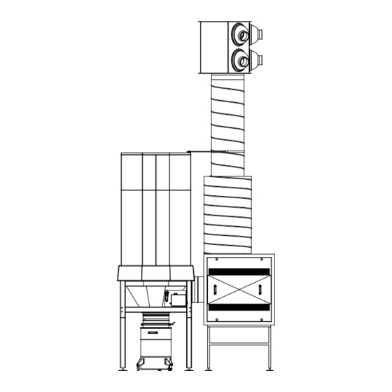
INSTALLATION TECHNICAL SPECIFICATIONS: Model#: AD1326-8 CIRCULATOR INPUT MAkE/MODEL DESCRIPTION INPUT VOLTAGE NOMINAL CURRENT +/- 10% (MAX.) CIRCULATOR AIR HANDLING 380-480V/3~/50-60Hz 13.9A PHYSICAL DIMENSIONS HEIGHT WIDTH DEPTH WEIGHT 213.6 in. 92.1 in. 53.2 in. 1764 lbs. 5425 mm 2340 mm 1350 mm 800 kg. -
Page 10: Safety
INSTALLATION READ ENTIRE INSTALLATION SECTION BEFORE Lifting STARTING INSTALLATION. Lifting this machine is NOT recommended without disas- sembly. If lifting or moving is necessary, follow the Safety Precautions Installation Procedure detailed in this manual. WARNING ELECTRIC SHOCk can kill. • Only qualified personnel should per- form this installation. -
Page 11: General Description
INSTALLATION GENERAL DESCRIPTION HARDWARE UNCRATING: TOOLS NEEDED The CIRCULATOR is a free-standing general filtration 13 mm Socket Wrench system that prevents accumulation of welding fume by 13 mm Open-end Wrench continuous filtration of polluted air. It consists of a Miscellaneous Hand Tools central filter unit, a fan in a sound absorbing case, an Ladder/Lift outlet unit with adjustable outlet nozzles, a silencer... - Page 12 INSTALLATION FIGURE A.3 Connecting Air Inlet To Filter Base 3. Using a 13mm wrench, secure the air inlet module to the filter housing with the four mounting nuts, bolts and washers provided. See Figure A.2. LOCK NUTS 4. Carefully place the labyrinth spark arrester (lower) WASHERS THREADED ROD inside the air inlet module.
- Page 13 INSTALLATION 2. Mount the adapter onto the connection ring. See 2. Insert leg connectors half way into leg frames. See Figure A.7. Figure A.5. 3. Do not slide the adapter all the way on to the con- 3. Insert bolts and washers into lower holes and hand nection ring.
- Page 14 INSTALLATION Connecting Outlet Unit Connection Of Silencer 1. Place the duct extension on top of the silencer. 1. Place a duct connector into the exhaust hole on Carefully maneuver into position so the previously the top of the fan cabinet. Secure into place using installed duct connector fits inside the extension eight self tapping screws.
- Page 15 INSTALLATION Particulate Collection Drum FIGURE A.12 1. Mount the flexible duct connector onto the drum flange and tighten the adjustable clamps using a slot head screwdriver. See Figure A.11. PRESSURE NOTE: Make sure the flexible duct covers and the REDUCING black rubber gasket are located on the drum VALVE flange.
- Page 16 INSTALLATION When Making Electrical Connections WARNING ELECTRIC SHOCk can kill. • Only qualified personnel should per- form this installation. • Turn the input power OFF and unplug the machine from the recep- tacle before working on this equip- ment. • insulate yourself from the work and ground. •...
-
Page 17: Operation
OPERATION PRODUCT DESCRIPTION INPUT VOLTAGE The CIRCULATOR is a free-standing general filtration system that prevents accumulation of welding fume by continuous filtration of polluted air. It consists of a central filter unit, a fan in a sound absorbing case, an INPUT CURRENT outlet unit with adjustable outlet nozzles, a silencer and a control panel with frequency inverter and PLC. -
Page 18: Control
OPERATION CONTROL The system is designed to run in automatic mode. In this time-controlled operation, the system will start and stop automatically at the preset days and times. WARning MAkE SURE THE HANDLE OF THE PARTICU- LATE COLLECTION DRUM IS IN THE VERTICAL (OPEN) POSITION. -
Page 19: Time Controlled Operation
OPERATION TIME CONTROLLED OPERATION • Move the “>” cursor to ‘ON’: Press t or s. • Confirm ‘ON’: Press Ok. 1. Turn on the main switch. See Figure B.1. The display shows: 2. Wait approx. 10 seconds for the system to initialize. 3. -
Page 20: Manual Operation
OPERATION The throw can be adjusted by the potentiometer FAN MANUAL OPERATION SPEED 0-100%. The fan speed ranges between To control the system manually, proceed as follows. 30Hz and 50Hz. The maximum throw is 130 ft. (40m) at an air velocity of 1 to 1.6 ft/s (0.3 to 0.5m/s). 1. -
Page 21: Adjustable Nozzle Positioning
OPERATION FIGURE B.2 - ADJUSTABLE NOzzLE POSITIONING Welding fume is mixed Preferred at source, optimum dilution Concentration of welding Not Recommended fume instead of dilution Preferred Example position of two systems Dilution/filtration of a specific section of the facility Preferred CIRCULATOR... -
Page 22: Velocity Graph
OPERATION FIGURE B.3 - VELOCITY GRAPH (m/s) (m/s) 0,25 V T = final velocity of throw V F = velocity of outlet nozzle L T = throw at VT q v = air volume per nozzle 7 8 1000 1500 2500 2000 3000... -
Page 23: Automatic System Start-Up
OPERATION 5. Press t or u to change cursor position. Press q AUTOMATIC SYSTEM START-UP to change value. 6. Press OK. 1. Follow Set Weekly Timer procedure. NOTE: Timer 1 - screen 4: make sure setting Pulse = Off. OVERTIME SYSTEM START-UP If desired, Timers 2 to 4 can be used to set additional on/off moments of the fan, resulting 1. -
Page 24: Maintenance
MAINTENANCE AUTOMATIC FILTER CLEANING Each time the system is switched off after having been run for at least 1.5 hours, an automatic cleaning cycle will take place. During this cycle, both filter car- tridges are cleaned by compressed air jets from the RotaPulsePlus system. -
Page 25: Maintenance Schedule
MAINTENANCE MAINTENANCE SCHEDULE MOTOR/FAN HOUSING (SOUND ABSORBING ENCLOSURE) NOTE: * REQUIRES Lincoln Electric factory autho- rized service technician. • Check the integrity of the fan housing (sound absorbing box) and tighten all bolts and screws if AS NEEDED necessary. • Replace filters (See filter replacement instructions). -
Page 26: Replacing The Filters
• In cases of a continuous alarm situation while the cleaning mechanism is running. NOTE: For all other technical issues, please contact The Lincoln Electric Automation Division NOTE: You must learn from experience when to Environmental Solutions Hotline at 1-888-935- replace the filters. -
Page 27: Troubleshooting
HOW TO USE TROUBLESHOOTING GUIDE WARNING Service and Repair should only be performed by Lincoln Electric Factory Trained Personnel. Unauthorized repairs performed on this equipment may result in danger to the technician and machine operator and will invalidate your factory warranty. For your safety and to avoid Electrical Shock, please observe all safety notes and precautions detailed throughout this manual. - Page 28 TROUBLESHOOTING Observe all Safety Guidelines detailed throughout this manual PROBLEMS POSSIBLE AREAS OF RECOMMENDED (SYMPTOMS) MISADJUSTMENTS(S) COURSE OF ACTION START-UP PROBLEMS When the “Start Button” is pressed 1. Make sure the correct input the system will not start. power is being applied. 2.
- Page 29 TROUBLESHOOTING Observe all Safety Guidelines detailed throughout this manual PROBLEMS POSSIBLE AREAS OF RECOMMENDED (SYMPTOMS) MISADJUSTMENTS(S) COURSE OF ACTION FUNCTION PROBLEMS The cooling fan inside the control 1. Check thermostat setting panel does not function. (inside panel). 2. Have an electrician check the electrical connections.
-
Page 30: Theory Of Operation
THEORY OF OPERATION GENERAL DESCRIPTION The Circulator system is self contained and is specifi- cally designed for the filtration and general removal of welding fume. It is suitable for continuous use in welding applications. The system features a control panel, a filter, a fan powered by a three phase motor and duct work. - Page 31 Keep your head out of fumes. Turn power off before servicing. Do not operate with panel open or WARNING Use ventilation or exhaust to guards off. remove fumes from breathing zone. Spanish Los humos fuera de la zona de res- Desconectar el cable de ali- No operar con panel abierto o AVISO DE...
- Page 32 Do not touch electrically live parts or Keep flammable materials away. Wear eye, ear and body protection. WARNING electrode with skin or wet clothing. Insulate yourself from work and ground. Spanish No toque las partes o los electrodos Mantenga el material combustible Protéjase los ojos, los oídos y el AVISO DE bajo carga con la piel o ropa moja-...
- Page 33 • World's Leader in Welding and Cutting Products • • Sales and Service through Subsidiaries and Distributors Worldwide • Cleveland, Ohio 44117-1199 U.S.A. TEL: 888.935.3878 FAX: 216.383.8823 WEB SITE: www.lincolnelectric.com...
Need help?
Do you have a question about the AD1326-8 and is the answer not in the manual?
Questions and answers