Advertisement
- 1 Functions
- 2 Applications
- 3 General description
- 4 Interface to the ventilation system
- 5 Selection of transmitters
- 6 Mounting location
- 7 Connection Diagram
- 8 Setting of the device to keep fan running in minimal volume in OFF mode
- 9 Parameter copy
- 10 View back part when front plate removed
- 11 Technical data
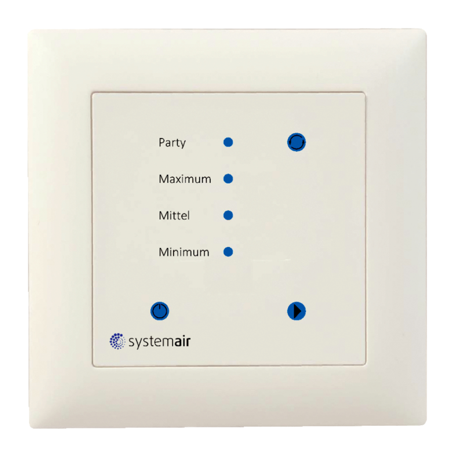
- 12 Display and operation
- 13 Documents / Resources
Functions
Positioner and controller for comfort ventilation with touch panel
- Design according to Feller EDIZIOdue®
- Manual operation with up to 4 steps
- AUTO operation: The controller activates the ventilation based on controls curve.
- Automatic reset of the Party air level
- One 0...10 VDC controls output to control the ventilation system
- One 0...10 VDC input to measure CO2 or other sensors
Applications
Control of ventilation systems for comfort applications. For example for well insulated residential areas which are required to be ventilated
General description
The MZ3-Touch is a microprocessor controlled precision positioner and controller with touch panel.
Interface to the ventilation system
The positioner works with all ventilation systems that are designed with a 0...10 VDC or 2...10 VDC input signal.
Selection of transmitters
The positioner works with all sensors that provide an output signal of 0...10 VDC or 2...10 VDC. The measuring range needs to be observed. For example: CO2 0...2000 ppm = 0...10 VDC or 2...10 VDC
Mounting location
On an easy accessible interior wall, approx. 1.5 m (4.5') above the floor. The MZ3-Touch is so designed that it can be incorporated into a commercially available flush box (Feller EDIZIOdue® frame and mounting plate are included).
Connection Diagram

Description:
| 1 | V+ | Power supply: | 24 VAC, +24 VDC |
| 2 | GND | Power supply: | 0 V, -24 VDC, internally connected to signal common |
| 3 | AI | Analog input for sensor | 0...10 VDC |
| 4 | AO | Analog output ventilation: | 0...10 VDC |
Setting of the device to keep fan running in minimal volume in OFF mode
If JP1 in position 1-2, the output is off in OFF mode.
Ventilation switches off.
If JP1 in position 2-3 or removed, the output stays in
OFF mode in Level 0 (minimum air volume)
Parameter copy
It is possible to copy settings to an accessory (AECPM2) and to copy them back to other MZ3. For this, remove the front panel of the MZ3, insert AEC-PM2 in the designated plug. Connect OPA-S and copy parameter from MZ3 to AEC-PM2 by setting OP05 to 1.
AEC-PM2 "Data" LED is ON for 5 seconds after successful parameter copy and OP05 is set to 0. If the parameter copy failed the LED blinks for 5 seconds and OP05 is set to 7.
Copy parameter from AEC-PM2 to MZ3 simply by pressing the "Copy" button on the AEC-PM2. AECPM2 "Data" LED is ON for 5 seconds after successful parameter copy. If the parameter copy failed the LED blinks for 5 seconds.
View back part when front plate removed

Technical data
Installation and safety advice
This device is intended to be used as positioner for comfort ventilation systems. Where a device failure endangers human life and/or property, it is the responsibility of the client to add additional safety devices to prevent or detect a system failure caused by such a device failure. The device contains electronic components and must not be disposed of with household waste.
| Power supply | Operating voltage | 24 V AC/DC ± 10%, 50/60 Hz, Class 2, 48 VA max |
| Power consumption | Max. 1.0 VA | |
| Electrical connection | Terminal Connectors, wire 0,34-2,5 mm2 (AWG 22...13) | |
| Signal inputs | Analog Input | 0...10 V DC |
| Signal outputs | Analog outputs Output signal Resolution Maximum load | - DC 0...10 V DC 9.76 mV (10 Bit) 10 mA or 1kΩ |
| Environment | Operation Climatic conditions Temperature Humidity | To IEC 721-3-3 class 3 K5 0...50°C (32...122°F) < 95% RH. non-condensing |
| Transport & storage Climatic conditions Temperature Humidity Mechanical conditions | To IEC 721-3-2 and IEC 721-3-1 class 3 K3 and class 1 K3 -25...70°C (-13...158°F) <95% RH non-condensing class 2MT2 | |
| Standards |  Conform to EMC Directive 2004/108/EC | EN 61 000-6-1/ EN 61 000-6-3 |
| Product standards Automatic electrical controls for household and similar use | EN 60 730-1 | |
| Degree of protection | Wall mounted: IP40 acc. EN 60529 Not installed: IP00 acc. EN 60529 | |
| Safety class | III (IEC 60536) | |
| General | Housing material: | Fireproof ABS+PC plastic (UL94 class V-0) |
| Dimensions (H x W x D) including packaging | 120 x 120 x 40 mm (4,7" x 4,7" x 1,6") | |
| Weight (incl. packaging) | 140 g (5.0 oz) |


Display and operation

ON/OFF operation
The device is activated by pressing the ON/OFF button. Depending on the position of JP1, the minimum air volume remains active even during OFF mode. In OFF mode, the operating mode symbol lights up with reduced intensity
Manual operation
If a sensor signal is detected at the input, the automatic operation of the device is enabled.
The following operation modes will be activated through repeated pressing of the step button:
Minimum = 1/5 Volumenstrom*
Normal = 2/5 Volumenstrom*
Maximum = 3/5 Volumenstrom*
Party = 5/5 Volumenstrom* for 2h, after which it will automatically switch to the 3/5 flow.
*Equal to the difference of Vmax to Vmax
Auto mode
In automatic mode, the volume flow is regulated on the basis of CO2 or air quality sensors. The operating modes are activated only after 10 seconds. This prevents unnecessary switching when setting the device.
AUTO operation
If a sensor signal is detected at the input, the automatic operation of the device is enabled. IP08 defines a time delay after which the unit returns to automatic operation once placed into manual.
Level Mode (IP00=ON)
The ventilation level is then activated based on the sensor signal and the limits defined under IP04 – IP06 Setting a level limit of IP05 – IP06 to 0, deactivates this level for automatic mode. The sensor signal will then not be able to activate this particular level.
Continuous Mode (IP00=OFF)
The ventilation is controlled gradually by the sensor signal. Instead of level steps, the output voltage is adjusted continuously. The sensor minimum and sensor maximum of the linear range can be set with IP04 and IP06. The output voltage then behaves linearly between OP00 and OP03.
Input configuration
| Parameter | Description | Range | Default |
| IP00 | Auto operation mode
| ON, OFF | ON |
| IP01 | Samples taken for averaging input signal | 1...255 | 3 |
| IP02 | Offset of input signal (Uout = Uset + Offset) | -10...10 | 0 |
| IP03 | Input signal type: OFF = 0-10V, ON = 2-10V | ON, OFF | OFF |
| IP04 |
| 0...100% | 40% |
| IP05 |
| 0...100% | 60% |
| IP06 |
| 0...100% | 80% |
| IP07 | Hysteresis of level mode | 0...100% | 10% |
| IP08 | Reset time manual to auto operation 0: Never reset | 0...255 min | 0 min |
 Note: If this level is set to 0, it is deactivated for level mode.
Output configuration
| Parameter | Description | Range | Default |
| OP00 | Output level 0, 0...100% = 0...10.0 VDC | 0...100% | 20% = 2 V |
| OP01 | Output level 1, Setting a level to 0 disables it | 0...100% | 40% = 4 V |
| OP02 | Output level 2, Setting a level to 0 disables it | 0...100% | 60% = 6 V |
| OP03 | Output level 3, Setting a level to 0 disables it | 0...100% | 100% = 10 V |
| OP04 | Automatic reset time of the highest level to the level defined in OP05. The reset is deactivated with setting = 0 | 0...255 min | 120 min |
| OP05 | Output level after automatic reset. This level will be activated once the reset time defined in OP04 has expired. | 0...2 | 0 |
| OP06 | 0: Parameter copy successful; No action 1: Start parameter copy to AEC-PM2 7: Copy fail (no AEC-PM2 or communication error) | 0-1 7: display only | 0 |

Documents / ResourcesDownload manual
Here you can download full pdf version of manual, it may contain additional safety instructions, warranty information, FCC rules, etc.
Download SystemAir MZ3-Touch - Controller/Positioner For Comfort Ventilation Manual
Advertisement


Need help?
Do you have a question about the MZ3-Touch and is the answer not in the manual?
Questions and answers