
Subscribe to Our Youtube Channel
Related Manuals for SystemAir SYSVRF AHU 5HP S


Summary of Contents for SystemAir SYSVRF AHU 5HP S
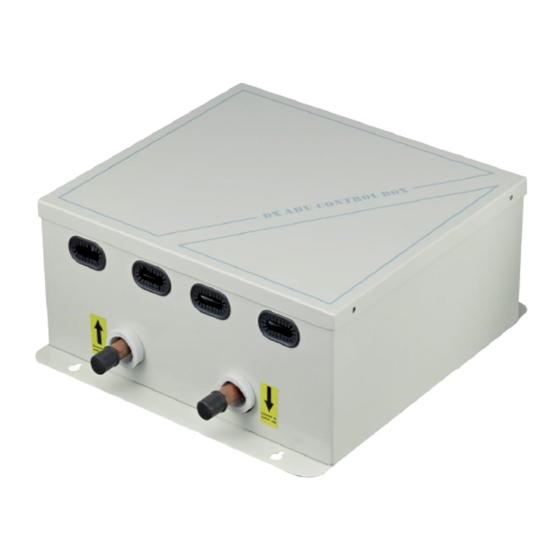
- Page 1 INSTALLATION & OWNER’S MANUAL SYSVRF AHU Box Thank you very much for purchasing our air conditioner, Before using your air conditioner , please read this manual carefully and keep it for future reference.
-
Page 3: Table Of Contents
CONTENTS PAGE When installing the unit in a small room, take measures against to keep refrigerant concentration from exceeding PRECAUTIONS..................allowable safety limits in the event of refrigerant leakage. Contact the place of purchase for more information. INSTALLATION INFORMATION..............Excessive refrigerant in a closed ambient can lead to oxygen ATTACHED FITTINGS................ -
Page 4: Installation Information
2. INSTALLATION INFORMATION If the refrigerant leaks during installation, ventilate the area immediately. Toxic gas may be produced if the refrigerant comes into the place contacting with fire. To install properly, please read this "installation manual" at first. After completing the installation work, check that the refrigerant does not leak. -
Page 5: Attached Fittings
Cautions on wire controller installation ● Never throw or beat the controller. This DX AHU box can be controlled by SYSTEMAIR controller and SIEMENS controller. If choose to use SYSTEMAIR controller, ● operate the wire controller to determine its location in a reception range. -
Page 6: Installation Method&Dimension
4. INSTALLATION METHOD & DIMENSION Units: mm AHU 5HP S AHU 10HP S AHU 20HP S Wire passing-hole Connect to indoor unit Connect to outdoor unit Install vertically Installation method : Hanging Fig.4-1 Wrong installation way Fig.4-2 NOTE The controller box can not installation in outdoor occasions,if inevitable,it must increase rainproof precautions,specific methods please contact the local dealar or technical support engineer. -
Page 7: Material And Size Of The Piping
5. MATERIAL AND SIZE OF THE PIPING 6-2 Size of joint pipe for 410A indoor unit Table.6-2 Capacity of Size of main pipe(mm) CAUTION controller box A(×100W) Liquid side(mm) Available branch joint The connecting distance of each control box and indoor unit should not more than 8 m. -
Page 8: Electrical Wiring
7. ELECTRICAL WIRING Table.7-3 The maxium current of AC motor Model AHU 5HP 3.5 A CAUTION AHU 10HP, 20HP 18 A The outdoor and indoor units should use separate power supply with rated voltage. but all the indoor units in the same system shoud be use the same power. - Page 9 7-4 Electric control box wiring figure Indoor temp sensor (T1), indoor evaporator intermediate temp sensor (T2), indoor evaporator outlet temp sensor (T2B), please connects respond to the wiring nameplate. Connector Fig.7-5 CAUTION SYSVRF AHU 5HP, 10HP, 20HP are applied one main control panel, the temperature sensor T1, T2 and T2B must connect to the main control board before first powered on ;...
-
Page 10: Applicaltion Control
8. APPLICALTION CONTROL thereinto, "heat exchanger copper pipe " refers to the copper tubes that are covered by fins.The tube is inner grooved copper tube.The fins is lourered fins. 8-1 Capacity setting 2)The volume of heat exchanger desinged is based on evaporating Set the dial switch ENC1 on the main control board by different temperature of 8℃,superheat of 4K, suction air temperature of 27℃... - Page 11 Shown as Table 8-3, DX AHU box with capacity dial code from 0 to 3) The indoor unit quantity detected by outdoor unit will be the sum A occupy 1 address. DX AHU box with capacity dial code of B of the actual address quantity and the virtual address quantity, occupies 2 addresses.
-
Page 12: Controller Selection
9. CONTROLLER SELECTION 9-2 SIEMENS controller The DX AHU box can be controlled by SYSTEMAIR controller and When SIEMENS controller has been selected, only SIEMENS SIEMENS controller. The status of SW3 on the main board will controller can be use to control the DX AHU box. The signal from decide which controller has been selected. - Page 13 M D4 D3 S Y1 M 14 13 34 44 54 53 Terminal block Power MP 24V D5 M INFO SIEMENS ALARM POL 638.70 33 34 SIEMENS controller Fig.9-4 Note, 1. The distance between SIMENS controller and DX AHU control box should less than or equal 15 m. 2.
-
Page 14: Definition Of Each Dial Switch
(Default setting) 1 means to connect SIEMENS 10. DEFINITION OF EACH DIAL SWITCH controller and non-auto restart function 0 means to connect SYSTEMAIR SW1 Definition controller and auto restart function (Default setting) Note:the quantity set of slave DX AHU control box only need in master indoor unit. -
Page 15: Trouble Shooting
11. TROUBLE SHOOTING Table.11-1 Type Contents Error code Remarks Recover to normal display until finish No address when first time Alarm The LED display show “FE” setting address power on M_home non-matching, The LED display show “H0” Alarm or connect with “MS” device Mode conflict The LED display show “E0”... - Page 16 MD14IU-033BW 202000172668...
Need help?
Do you have a question about the SYSVRF AHU 5HP S and is the answer not in the manual?
Questions and answers