
Subscribe to Our Youtube Channel
Related Manuals for SystemAir RETP6


Summary of Contents for SystemAir RETP6
- Page 1 RETP6 / RETP10 Multipurpose controller for variable voltage 1 ~ fans Operating Instructions Software version: B1061AA from version 1.01 L-BAL-E082-GB 1237 Index 002 Part.-No. 00163339-GB...
-
Page 2: Table Of Contents
Operating Instructions RETP6 / RETP10 Content General notes ............. - Page 3 Operating Instructions RETP6 / RETP10 Base setup ............. . .
-
Page 4: General Notes
Operating Instructions RETP6 / RETP10 General notes 1 General notes Structure of the operating instructions Before installation and start-up, read this manual carefully to ensure correct use! We emphasize that these operating instructions apply to specific units only, and are in no way valid for the complete system! Use these operating instructions to work safely with and on the device. -
Page 5: Product Safety
Operating Instructions RETP6 / RETP10 Safety instructions Danger due to electric current Warning of dangerous voltage or dangerous current. Information Important additional information and advice for user. Product safety The device conforms to the state of the art at the time of delivery and is fundamentally considered to be reliable. -
Page 6: Modifications / Interventions In The Device
Operating Instructions RETP6 / RETP10 Product overview Danger due to electric current It is generally forbidden to carry out work on electrical live parts. Protection class of the device when open is IP 00! It is possible to touch hazardous voltages directly! The safe isolation from the supply must be checked using a two-pole voltage detector. -
Page 7: Storage
Operating Instructions RETP6 / RETP10 Mounting Storage • The device must be stored in its original packaging in a dry and weather-proof room. • Avoid exposure to extreme heat and cold. • Avoid over-long storage periods (we recommend a maximum of one year). -
Page 8: Installation Location For Agriculture
Operating Instructions RETP6 / RETP10 Electrical installation Installation location for agriculture In order to avoid damage caused by ammoniac vapours, the controller shall not be installed in the stable, but rather in an outhouse wherever possible. Temperature influences during commissioning... -
Page 9: Mains Connection
Operating Instructions RETP6 / RETP10 Electrical installation Mains connection Power from the mains is connected to terminals: PE, L1 and N. Here, it must be strictly observed that the mains voltage lies within the allowable tolerance specifications ( Technical data and nameplate affixed to the side). -
Page 10: Output Voltage 0 - 10 V (A1 = Analog Out 1)
Operating Instructions RETP6 / RETP10 Electrical installation • For sensors in two-wire-technology (4 - 20 mA signal), the connection is made on the “+24 V” and “E1” (“GND” terminal is omitted). Over DIP 4 an inverting of the input is possible for mode 1.01... -
Page 11: Enable, Device On / Off
Operating Instructions RETP6 / RETP10 Electrical installation 5.9.1 Enable, device ON / OFF Electronic disconnection and Reset after motor fault via floating contact at terminals “D1” - “D1” • Device “ON” for closed contact. • Device “OFF” with opened contact. -
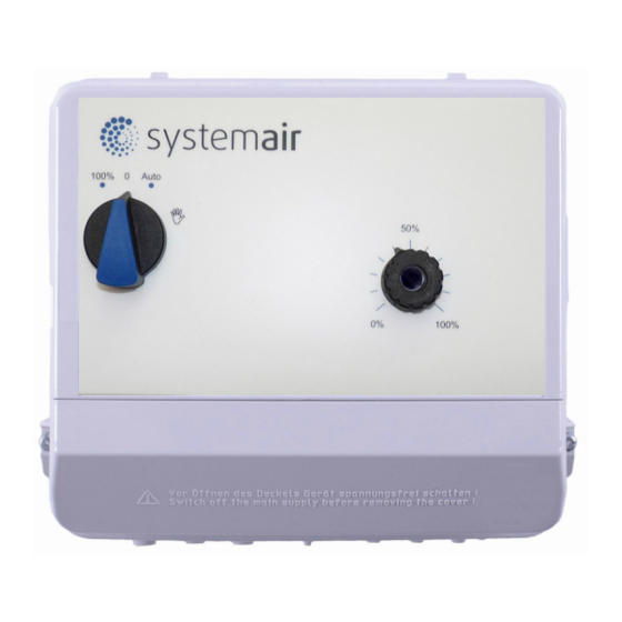
Page 12: Operating And Display Elements
Operating Instructions RETP6 / RETP10 Operating and display elements 6 Operating and display elements Main switch and potentiometer with integrated light signal 17.09.2012 v_retp_front_bed.VSD Main switch Position Function Ventilators are operated directly from the mains with no control. 100 %... -
Page 13: Internal Setting
Operating Instructions RETP6 / RETP10 Operating and display elements Internal Setting Attention! The controller housing cover may only be removed when the power line has been switched off! It is generally forbidden to carry out work on electrical live parts. Protection class of the device when... -
Page 14: Base Setup
Operating Instructions RETP6 / RETP10 Base setup 7 Base setup Programming of the desired function (Speed controller / P-Controller, PI-Controller) • It is possible to use the device as a Speed controller or as a P-controller, PI-Controller. Selection of the function must first be made by setting the internal jumper “E1” and dipswitch “S1”. -
Page 15: Function Of Dipswitches For Operation As Speed Controller (Dip 1 = Off )
Operating Instructions RETP6 / RETP10 Base setup Function of dipswitches for operation as Speed controller 1.01 (DIP 1 = For operation as a speed controller (main switch = Auto), the output voltage is set manually by adjusting the built-in potentiometer, by an external potentiometer or external signal. -
Page 16: Minimum Speed Cut Off Dip 5
Operating Instructions RETP6 / RETP10 Base setup Minimum speed cut off DIP 5 1.01 7.5.1 For mode Speed controller If no “n-min” is adjusted,output voltage goes continuously with reduction of the regulating variable down to “0” (cutoff below approx. 2 % regulating variable). -
Page 17: Start-Up
Operating Instructions RETP6 / RETP10 Start-up Start-up Prerequisites for commissioning Attention! 1. You must mount and connect the device in accordance with the operating instructions. 2. Double check that all connections are correct. 3. The mains voltage must match the information on the rating plate. -
Page 18: Diagram: Setting Signal And Speed
Operating Instructions RETP6 / RETP10 Setting for operation 9.1.2 Diagram: setting signal and speed 100 % Min. 0 % Max. = 100 % Min. 35 % Max. = 85 % 50 % Min. 0 – 10 V 10 – 0 V 0 –... -
Page 19: Temperaturre Control (P-Controller) 2.01
Operating Instructions RETP6 / RETP10 Setting for operation Temperaturre control (P-Controller) 2.01 9.2.1 Setting for operation as Temperature controller Setpoint setting alternatively by “potentiometer inside” (DIP 2 = ) or “potenti- ometer outside” (DIP 2 = For control with active sensors (0 - 10 V, 4 - 20 mA) 08.02.2008... -
Page 20: Example Temperature Control "Cooling Function" (Factory Setting)
Operating Instructions RETP6 / RETP10 Setting for operation “Cooling function” 9.2.2 Example Temperature control (factory setting) • “Val > Set = n+” (DIP4 = • Temperature sensor type TF.. • Measuring range controller -26...+76 °C Settings: • set = 50 % 25 °C (102 K / 100 % x 50 % - 26 °C) -
Page 21: Pressure Control Condensers (P-Controller) 3.01
Operating Instructions RETP6 / RETP10 Setting for operation Pressure control condensers (P-Controller) 3.01 9.3.1 Setting for operation as Pressure controller Setpoint setting alternatively by “potentiometer inside” (DIP 2 = ) or “potenti- ometer outside” (DIP 2 = 08.02.2008 v_set_pxet.VSD For control with active sensors (0 - 10 V, 4 - 20 mA) -
Page 22: Example Pressure Control Condensers
Operating Instructions RETP6 / RETP10 Setting for operation 9.3.2 Example Pressure control condensers Pressure sensor • Type MBG-30I • Measuring range 0 - 30 bar • Output signal 4...20 mA Settings: • set = 50 % 15.0 bar, in use of refrigerant medium table for R507 •... -
Page 23: Setting With Refrigerant Medium Table
Operating Instructions RETP6 / RETP10 Setting for operation 9.3.3 Setting with refrigerant medium table Information Calculation for relative pressure (differential measurement of pressure relative to ambient pressure). MBG-30I 0.00 1.50 3.00 4.50 6.00 7.50 9.00 10.50 12.00 13.50 15.00 16.50 18.00... -
Page 24: Pressure Control, Air Velocity Control (Pi-Controller) 4.01
Operating Instructions RETP6 / RETP10 Setting for operation Pressure control, Air velocity control (PI-Controller) 4.01 9.4.1 Setting for operation as Pressure and air velocity controller Setpoint setting alternatively by “potentiometer inside” (DIP 2 = ) or “potenti- ometer outside” (DIP 2 = For control with active sensors (0 - 10 V, 4 - 20 mA) 08.02.2008... -
Page 25: Diagnostics / Faults
Operating Instructions RETP6 / RETP10 Diagnostics / Faults 10 Diagnostics / Faults Operating states are indicated by the rotary control’s integrated light signal and, at the same time, using the internal status LED by a flashing code. Relay Reaction of Controller... -
Page 26: If Controller Doesn´t Work Correctly
Operating Instructions RETP6 / RETP10 Enclosure 10.1 If controller doesn´t work correctly Information Setting of dip switches in principle only when device is not under voltage. If the device is on mains supply modifications will partly not be identified and realized. -
Page 27: Performance Reduction During Elevated Ambient Temperatures
Operating Instructions RETP6 / RETP10 Enclosure 11.1.1 Performance reduction during elevated ambient temperatures The maximum permissible ambient temperature for the devices is 40 °C. Up to this temperature, loading (maximum continuous current) with the specified rated current is possible. The removal of heat in the unit due to power dissipation is dependent on the ambient temperature, so the maximum load has to be reduced if the ambient temperature is higher than 40 °C! For each degree... -
Page 28: Connection Diagram
Operating Instructions RETP6 / RETP10 Enclosure 11.2 Connection diagram ...6 F1=M10 A / ...10 F1=FF20 A RETP6/10 Hand/Auto °C 100 % Kontaktbelastung Contact rating max. AC 250 V 5 A A1 GND E1 GND Eingang Input 0...10 V 0...20 mA Netz 4...20 mA... -
Page 29: Dimensions [Mm]
Operating Instructions RETP6 / RETP10 Enclosure 11.3 Dimensions [mm] RETP6 RETP10 L-BAL-E082-GB 1237 Index 002 Part.-No. 00163339-GB 29/31... -
Page 30: Index
Operating Instructions RETP6 / RETP10 > 11.4 Index basic speed Technical data 3, 26 bypass circuit The motor can be protected two steps two-wire-technology control cable control function voltage regulation external potentiometer external signal heat dissipation Input resistance internal potentiometer... -
Page 31: Manufacturer Reference
Operating Instructions RETP6 / RETP10 Index 11.5 Manufacturer reference Our products are manufactured in accordance with the relevant international regulations. If you have any questions concerning the use of our products or plan special uses, please contact: Systemair Industrievägen 3...
Need help?
Do you have a question about the RETP6 and is the answer not in the manual?
Questions and answers