Sign In
Upload
Manuals
Brands
Beckhoff Manuals
I/O Systems
EL3751
Beckhoff EL3751 1-channel analog input Manuals
Manuals and User Guides for Beckhoff EL3751 1-channel analog input. We have
1
Beckhoff EL3751 1-channel analog input manual available for free PDF download: Documentation
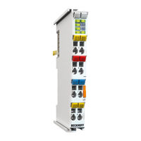
Beckhoff EL3751 Documentation (270 pages)
1-channel multi-functional input for measurement technology
Brand:
Beckhoff
| Category:
I/O Systems
| Size: 13.03 MB
Table of Contents
Fig. 1 EL2872 with Revision 0022 and Serial Number 01200815
12
Fig. 2 BIC as Data Matrix Code (DMC, Code Scheme ECC200)
12
Fig. 3 Example DMC 1P072222Sbtnk4P562D71Kel1809 Q1 51S678294
13
Fig. 4 EL3751, EL3751-0004, EL3751-0024; Leds, Connections and Assignment
17
Fig. 5 Basic Range of a Process Data Value
20
Fig. 6 Representation ±30 V Measurement Range
27
Fig. 7 Frequency Response ±30 V Measurement Range, Fsampling = 10 Khz, Integrated Filter 1/2 De- Activated
27
Fig. 8 Representation ±10 V Measurement Range
29
Fig. 9 Frequency Response ±10 V Measurement Range, Fsampling = 10 Khz, Integrated Filter 1/2 De- Activated
29
Fig. 10 Representation ±5 V Measurement Range
31
Fig. 11 Frequency Response ±5 V Measurement Range, Fsampling = 10 Khz, Integrated Filter 1/2 Deac- Tivated
31
Fig. 12 Representation ±2.5 V Measurement Range
33
Fig. 13 Frequency Response ±2.5 V Measurement Range, Fsampling = 10 Khz, Integrated Filter 1/2 De- Activated
33
Fig. 14 Representation ±1.25 V Measurement Range
35
Fig. 15 Frequency Response ±1.25 V Measurement Range, Fsampling = 10 Khz, Integrated Filter 1/2 Deactivated
35
Fig. 16 Representation ±640 MV Measurement Range
37
Fig. 17 Frequency Response ±640 MV Measurement Range, Fsampling = 10 Khz, Integrated Filter 1/2 Deactivated
37
Fig. 18 Representation ±320 MV Measurement Range
39
Fig. 19 Frequency Response ±320 MV Measurement Range, Fsampling = 10 Khz, Integrated Filter 1/2 Deactivated
39
Fig. 20 Representation ±160 MV Measurement Range
41
Fig. 21 Frequency Response ±160 MV Measurement Range, Fsampling = 10 Khz, Integrated Filter 1/2 Deactivated
41
Fig. 22 Representation ±80 MV Measurement Range
43
Fig. 23 Frequency Response ±80 MV Measurement Range, Fsampling = 10 Khz, Integrated Filter 1/2 Deactivated
43
Fig. 24 Representation ±40 MV Measurement Range
45
Fig. 25 Frequency Response ±40 MV Measurement Range, Fsampling = 10 Khz, Integrated Filter 1/2 Deactivated
45
Fig. 26 Representation ±20 MV Measurement Range
47
Fig. 27 Representation ±10 MV Measurement Range
49
Fig. 28 Representation ±5 MV Measurement Range
51
Fig. 29 Representation 0
53
Fig. 30 Frequency Response 0
53
Fig. 31 Representation 0
55
Fig. 32 Frequency Response 0
55
Fig. 33 Representation Current Measurement Range ±20 Ma
57
Fig. 34 Frequency Response ±20 Ma Measurement Range, Fsampling = 10 Khz, Integrated Filter 1/2 Deactivated
57
Fig. 35 Representation Current Measurement Range 0
59
Fig. 36 Frequency Response 0
59
Fig. 37 Representation Current Measurement Range 4
61
Fig. 38 Frequency Response 4
62
Fig. 39 Chart: Current Measuring Range 3.6
64
Fig. 40 Frequency Response 20 Ma Measurement Range, Fsampling = 10 Khz, Integrated Filter 1/2 De- Activated
64
Fig. 41 Representation Resistance Measurement Range 5 Kω
68
Fig. 42 Chart: RTD Measuring Range
69
Fig. 43 Representation Potentiometer Measurement Range
73
Fig. 44 Representation Measuring Range SG 1/1 Bridge
78
Fig. 45 Representation Measuring Range SG 1/2 Bridge
84
Fig. 46 Representation Measuring Range SG 1/4 Bridge 120 Ω
88
Fig. 47 Representation Measuring Range SG 1/4 Bridge 350 Ω
92
Fig. 48 Opening the *. Tnzip Archive
105
Fig. 49 Search of the Existing HW Configuration for the Ethercat Configuration of the Example
106
Fig. 50 Process of Interlacing the Input Data
119
Fig. 51 Configuration and Setup for Sample Program 6: Doubling of the Sample Rate with 2 X EL3751
119
Fig. 52 Setting the DC Shift Time for Terminal 2
120
Fig. 53 Oversampling 20 Ksps with 2 X EL3751 with Input Signals (Below) and Result Signal (Top)
121
Fig. 54 Oversampling 20 Ksps with 2 X EL3751 Shows Input Value 1 and Input Value 2 Alternately for a Result Value
122
Fig. 55 Decimation from 20 Μs (Left) to 22.675
125
Fig. 56 Function Block as an Example for Analysis of Diagnostics Information of the Terminal
128
Fig. 57 Creation of PDO Variables (Twincat Version >= V3.1.4024.0)
129
Fig. 58 Creation of the Smpdovariables (Twincat Version >= V3.1.4022.30)
130
Fig. 59 Seek the Generated Data Type of Smpdovariables
130
Fig. 60 Visualization of the Sample Implementation: Calibration Signature
131
Fig. 61 Selection of the Diagnostic Information of an Ethercat Slave
134
Fig. 62 Basic Ethercat Slave Diagnosis in the PLC
135
Fig. 63 EL3102, Coe Directory
137
Fig. 64 Example of Commissioning Aid for a EL3204
138
Fig. 65 Default Behaviour of the System Manager
139
Fig. 66 Default Target State in the Slave
139
Fig. 67 PLC Function Blocks
140
Fig. 68 Illegally Exceeding the E-Bus Current
141
Fig. 69 Warning Message for Exceeding E-Bus Current
141
Fig. 70 Relationship between User Side (Commissioning) and Installation
142
Fig. 71 Control Configuration with Embedded PC, Input (EL1004) and Output (EL2008)
143
Fig. 72 Initial Twincat 2 User Interface
144
Fig. 73 Selection of the Target System
145
Fig. 74 Specify the PLC for Access by the Twincat System Manager: Selection of the Target System
145
Fig. 75 Select "Scan Devices
146
Fig. 76 Automatic Detection of I/O Devices: Selection of the Devices to be Integrated
146
Fig. 77 Mapping of the Configuration in the Twincat 2 System Manager
147
Fig. 78 Reading of Individual Terminals Connected to a Device
147
Advertisement
Advertisement
Related Products
Beckhoff ELX4181 Series
Beckhoff EtherCAT EL600x Series
Beckhoff EtherCAT EL6022
Beckhoff EtherCAT EL602x Series
Beckhoff EtherCAT EL6001
Beckhoff EtherCAT EL6021
Beckhoff EtherCAT EL6002
Beckhoff EL2911
Beckhoff EPP2 Series
Beckhoff ERI2809-0021
Beckhoff Categories
Touch terminals
Industrial PC
Control Unit
Touch Panel
Power Supply
More Beckhoff Manuals
Login
Sign In
OR
Sign in with Facebook
Sign in with Google
Upload manual
Upload from disk
Upload from URL