Table of Contents
Advertisement
Quick Links
www.ti.com
EVM User's Guide: TMUX4827YBHEVM
TMUX4827YBH Evaluation Module
Description
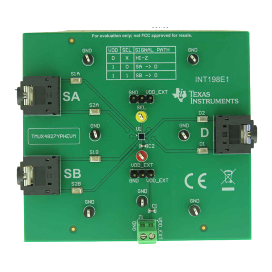
The TMUX4827YBHEVM is used to evaluate the
performance of the TMU4827. The evaluation module
(EVM) comes with a TMUX4827YBH device soldered
on. The EVM allows for an easy way for engineers
to evaluate the TMUX4827 with audio signals by
using on board audio jacks. Additionally, test points
on board are provided to allow for the capability to test
for signals that aren't audio signals as well.
SCDU034 – MAY 2023
Submit Document Feedback
Features
•
TMUX4827YBH pre-soldered on board
•
2 power supply decoupling capacitor from VDD to
Ground (1µF 0402; 0.1µF 0402)
•
6 test points on I/O's supporting TMUX4827 full
current capabilities
•
7 additional GND test points for easy of probing
•
1 3-pin header for connecting/disconnecting device
from external power
•
1 3-pin header to change signal path state of
device
TMUX4827YBHEVM (Top View)
Copyright © 2023 Texas Instruments Incorporated
Description
TMUX4827YBH Evaluation Module
1
Advertisement
Table of Contents

Related Manuals for Texas Instruments TMUX4827YBHEVM


Summary of Contents for Texas Instruments TMUX4827YBHEVM
- Page 1 Description EVM User's Guide: TMUX4827YBHEVM TMUX4827YBH Evaluation Module Description Features The TMUX4827YBHEVM is used to evaluate the • TMUX4827YBH pre-soldered on board performance of the TMU4827. The evaluation module • 2 power supply decoupling capacitor from VDD to (EVM) comes with a TMUX4827YBH device soldered Ground (1µF 0402;...
-
Page 2: Kit Contents
1.3 Specification The TMUX4827YBHEVM is used for quick prototyping of the TMUX4827 in the YBH package. The EVM has two 3-pin headers. One header for toggling the SEL pin to switch control the signal path routing of the device. The other 3-pin header allows for the VDD supply to be connected to an external source, to the board ground or left floating. - Page 3 VDD_EXT test point to provide a passive signal pathway between the Sx and Dx pins in according to the logic selected. 2.2 Header and Jumper Information The TMUX4827YBHEVM has two 3-pin headers to control the power supply connection, location C2 of the TMUX4827, and the control inputs, location A2. 1. Supply Header J2 Header J2 connects the VDD pin to either the external power or to ground via a jumper.
-
Page 4: Test Points
Hardware www.ti.com Figure 2-3. TMUX4827YBHEVM Truth Table 2.3 Test Points The board has a total of 15 test points. 7 GND, 1 SEL, 1 VDD, and 6 I/O. Test Point ID Description Signal Surface Mount Surface Mount Surface Mount Surface Mount... - Page 5 Hardware Design Files 3 Hardware Design Files The following section includes hardware design files for TMUX4827YBHEVM. This section includes the board level schematic, PCB layout and Bill of materials (BOM). 3.1 Schematics Figure 3-1. TMUX4827YBHEVM Schematic SCDU034 – MAY 2023...
-
Page 6: Pcb Layouts
Hardware Design Files www.ti.com 3.2 PCB Layouts Figure 3-2. TMUX4827YBHEVM Top Layer Layout Figure 3-3. TMUX4827YBHEVM Bottom Layer Layout TMUX4827YBH Evaluation Module SCDU034 – MAY 2023 Submit Document Feedback Copyright © 2023 Texas Instruments Incorporated... -
Page 7: Bill Of Materials (Bom)
Compatible Logic VDD_EXT Test Point, Multipurpose, Red, TH Keystone Electronics 5010 4 Additional Information 4.1 Trademarks All trademarks are the property of their respective owners. SCDU034 – MAY 2023 TMUX4827YBH Evaluation Module Submit Document Feedback Copyright © 2023 Texas Instruments Incorporated... - Page 8 STANDARD TERMS FOR EVALUATION MODULES Delivery: TI delivers TI evaluation boards, kits, or modules, including any accompanying demonstration software, components, and/or documentation which may be provided together or separately (collectively, an “EVM” or “EVMs”) to the User (“User”) in accordance with the terms set forth herein.
- Page 9 www.ti.com Regulatory Notices: 3.1 United States 3.1.1 Notice applicable to EVMs not FCC-Approved: FCC NOTICE: This kit is designed to allow product developers to evaluate electronic components, circuitry, or software associated with the kit to determine whether to incorporate such items in a finished product and software developers to write software applications for use with the end product.
- Page 10 www.ti.com Concernant les EVMs avec antennes détachables Conformément à la réglementation d'Industrie Canada, le présent émetteur radio peut fonctionner avec une antenne d'un type et d'un gain maximal (ou inférieur) approuvé pour l'émetteur par Industrie Canada. Dans le but de réduire les risques de brouillage radioélectrique à...
- Page 11 www.ti.com EVM Use Restrictions and Warnings: 4.1 EVMS ARE NOT FOR USE IN FUNCTIONAL SAFETY AND/OR SAFETY CRITICAL EVALUATIONS, INCLUDING BUT NOT LIMITED TO EVALUATIONS OF LIFE SUPPORT APPLICATIONS. 4.2 User must read and apply the user guide and other available documentation provided by TI regarding the EVM prior to handling or using the EVM, including without limitation any warning or restriction notices.
- Page 12 Notwithstanding the foregoing, any judgment may be enforced in any United States or foreign court, and TI may seek injunctive relief in any United States or foreign court. Mailing Address: Texas Instruments, Post Office Box 655303, Dallas, Texas 75265 Copyright © 2023, Texas Instruments Incorporated...
-
Page 13: Important Notice
TI products. TI’s provision of these resources does not expand or otherwise alter TI’s applicable warranties or warranty disclaimers for TI products. TI objects to and rejects any additional or different terms you may have proposed. IMPORTANT NOTICE Mailing Address: Texas Instruments, Post Office Box 655303, Dallas, Texas 75265 Copyright © 2023, Texas Instruments Incorporated...
Need help?
Do you have a question about the TMUX4827YBHEVM and is the answer not in the manual?
Questions and answers