Table of Contents
Advertisement
Quick Links
www.ti.com
User's Guide
TMUX9832BGAEVM User's Guide
This document is the EVM user's guide for the TMUX9832BGAEVM, which provides a quick way to evaluate TI's
TMUX9832 multiplexer device in the ZEH (BGA) package.
1
Introduction.............................................................................................................................................................................3
4
Features...................................................................................................................................................................................6
5 TMUX9832BGAEVM GUI Software Installation....................................................................................................................
5.1 GUI Software Installation...................................................................................................................................................
Start...................................................................................................................................................8
6 TMUX9832BGAEVM Setup Procedure..................................................................................................................................
7 TMUX9832BGAEVM Feature Descriptions.........................................................................................................................
7.1 SET and CLR Pin Operation............................................................................................................................................
7.3 TX7516 Pulser Interface Headers....................................................................................................................................
7.4 External SPI and LVDS....................................................................................................................................................
7.5 Thermal Shutdown...........................................................................................................................................................
7.6 Daisy Chain Operation.....................................................................................................................................................
Options.................................................................................................................................................14
8 Connection Descriptions.....................................................................................................................................................
9
Schematic..............................................................................................................................................................................17
10 Bill of Materials...................................................................................................................................................................
History..................................................................................................................................................................23
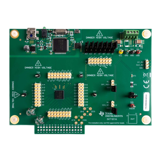
Figure 1-1. TMUX9832BGAEVM (Top View)...............................................................................................................................
Figure 1-2. TMUX9832BGAEVM (Bottom View).........................................................................................................................
Figure 5-1. Download Icon for TMUXHV-EVM GUI.....................................................................................................................
Figure 5-3. TMUXHV-EVM GUI...................................................................................................................................................
Figure 7-2. SPI_MODE and DIN_SEL Select Headers.............................................................................................................
Figure 7-3. Pulser Interface Headers.........................................................................................................................................
Figure 7-4. SPI Headers............................................................................................................................................................
Figure 7-5. LVDS Resistors.......................................................................................................................................................
Figure 7-6. Thermal Shutdown Indicator...................................................................................................................................
Figure 7-7. Daisy Chain Headers..............................................................................................................................................
Figure 7-8. Resistor and Capacitor Loading Footprints.............................................................................................................
Figure 9-1. TMUX9832BGAEVM Schematic.............................................................................................................................
Figure 9-2. TMUX9832BGAEVM Schematic.............................................................................................................................
Materials........................................................................................................................................................19
SCDU031B - JULY 2022 - REVISED FEBRUARY 2024
Submit Document Feedback
ABSTRACT
Table of Contents
Warnings..........................................................................................................................6
Operation...............................................................................................................................10
List of Figures
Diagram.......................................................................................................4
Tab..................................................................................................................................8
Buttons.............................................................................................................10
List of Tables
Supplies.........................................................................................................................9
Copyright © 2024 Texas Instruments Incorporated
Table of Contents
Guidelines...............................5
TMUX9832BGAEVM User's Guide
6
6
9
10
10
11
11
13
14
16
19
3
4
7
8
10
11
11
12
13
14
15
17
18
1
Advertisement
Table of Contents

Subscribe to Our Youtube Channel
Related Manuals for Texas Instruments TMUX9832BGAEVM


Summary of Contents for Texas Instruments TMUX9832BGAEVM
-
Page 1: Table Of Contents
Table of Contents User's Guide TMUX9832BGAEVM User's Guide ABSTRACT This document is the EVM user’s guide for the TMUX9832BGAEVM, which provides a quick way to evaluate TI’s TMUX9832 multiplexer device in the ZEH (BGA) package. Table of Contents Introduction.....................................3 2 General Texas Instruments High Voltage Evaluation Module (TI HV EVM) User Safety Guidelines.......5... - Page 2 Trademarks www.ti.com Trademarks ™ is a trademark of USB Implementers Forum. Texas Instruments ™ is a trademark of Texas Instruments. Chrome ™ is a trademark of Google LLC. Firefox ™ is a trademark of Mozilla Foundation. Safari ™ is a trademark of Apple Inc.
-
Page 3: Introduction
Introduction 1 Introduction This user's guide describes the TMUX9832BGAEVM evaluation module (EVM) and the intended use. This board allows for the quick prototyping and evaluation of TI’s TMUX9832ZEH multiplexer. The TMUX9832 is a 32-channel low harmonic distortion, low resistance, low capacitance, high-voltage, analog switch integrated circuit (IC) with latch-up immunity. -
Page 4: Figure 1-2. Tmux9832Bgaevm (Bottom View)
Figure 1-2. TMUX9832BGAEVM (Bottom View) Power Terminal Block SPI Controller Isolator Daisy Chain Outputs TMUX9832 Digital Controls Figure 1-3. TMUX9832BGAEVM Functional Block Diagram TMUX9832BGAEVM User's Guide SCDU031B – JULY 2022 – REVISED FEBRUARY 2024 Submit Document Feedback Copyright © 2024 Texas Instruments Incorporated... -
Page 5: General Texas Instruments High Voltage Evaluation Module (Ti Hv Evm) User Safety Guidelines
General Texas Instruments High Voltage Evaluation Module (TI HV EVM) User Safety Guidelines 2 General Texas Instruments High Voltage Evaluation Module (TI HV EVM) User Safety Guidelines WARNING Always follow TI’s setup and application instructions, including use of all interface components within their recommended electrical rated voltage and power limits. -
Page 6: Information About Cautions And Warnings
Internet Explorer is not supported. Users can access the live version through the link a Texas Instruments representative provides. 2. Click on the application icon within the gallery to launch the software. Click on the prompt to install the TI Cloud Agent Bridge browser plugin. -
Page 7: Figure 5-1. Download Icon For Tmuxhv-Evm Gui
TMUX9832BGAEVM GUI Software Installation Figure 5-1. Download Icon for TMUXHV-EVM GUI SCDU031B – JULY 2022 – REVISED FEBRUARY 2024 TMUX9832BGAEVM User's Guide Submit Document Feedback Copyright © 2024 Texas Instruments Incorporated... -
Page 8: Gui Software Quick Start
‘high’ state and dimmed for ‘low’ state. The effects of this functionality can be found in the data sheet. Figure 5-3. TMUXHV-EVM GUI TMUX9832BGAEVM User's Guide SCDU031B – JULY 2022 – REVISED FEBRUARY 2024 Submit Document Feedback Copyright © 2024 Texas Instruments Incorporated... -
Page 9: Tmux9832Bgaevm Setup Procedure
Powering up or down the TMUX9832BGAEVM in an arbitrary sequence can cause damage to the device. 4. Connect the mini-USB between the PC and TMUX9832BGAEVM connector J23 to power up the SPI communication block. The green LED (D1) next to J23 illuminates indicating that power is good. -
Page 10: Tmux9832Bgaevm Feature Descriptions
OFF. The DIN_SEL pin state must not be toggled during any SPI transmission. Figure 7-2. SPI_MODE and DIN_SEL Select Headers TMUX9832BGAEVM User's Guide SCDU031B – JULY 2022 – REVISED FEBRUARY 2024 Submit Document Feedback Copyright © 2024 Texas Instruments Incorporated... -
Page 11: Tx7516 Pulser Interface Headers
Figure 7-3. Pulser Interface Headers 7.4 External SPI and LVDS The TMUX9832BGAEVM enables the user to configure the board for use with the integrated SPI controller and GUI, or to provide an external SPI/LVDS communications setup. To provide an external communications setup, the user must leave the J14-J20 jumpers uninstalled to prevent unintended operation of the EVM. -
Page 12: Figure 7-5. Lvds Resistors
LVDS component footprints located on the reverse side of the board for the user to install resistors for an LVDS setup. Figure 7-5. LVDS Resistors TMUX9832BGAEVM User's Guide SCDU031B – JULY 2022 – REVISED FEBRUARY 2024 Submit Document Feedback Copyright © 2024 Texas Instruments Incorporated... -
Page 13: Thermal Shutdown
When the TMUX9832ZEH enters thermal shutdown, the /THERM pin asserts low and all switches is disabled. The TMUX9832BGAEVM implements an easy to identify thermal shutdown indicator circuit in which an LED illuminates if the device enters this condition (only if the J13 header is placed on the EVM). Once the device exits the thermal shutdown state, the LED turns off, the switches assumes the appropriate state based on the current digital input conditions, and the /THERM pin goes into a high impedance state. -
Page 14: Daisy Chain Operation
7.7 Channel Loading Options The TMUX9832BGAEVM features resistor and capacitor footprints (located on the backside of the board) to let the user install their own RC loads to evaluate the TMUX9832ZEH. Each input and output have a set of RC load footprints for maximum flexibility of the loading setup. -
Page 15: Figure 7-8. Resistor And Capacitor Loading Footprints
TMUX9832BGAEVM Feature Descriptions Figure 7-8. Resistor and Capacitor Loading Footprints SCDU031B – JULY 2022 – REVISED FEBRUARY 2024 TMUX9832BGAEVM User's Guide Submit Document Feedback Copyright © 2024 Texas Instruments Incorporated... -
Page 16: Connection Descriptions
RS0-RS31 Load resistor footprints (S-pins) RD0-RD31 Load resistor footprints (D-pins) CS0-CS31 Load capacitor footprints (S-pins) CD0-CD31 Load capacitor footprints (D-pins) TMUX9832BGAEVM User's Guide SCDU031B – JULY 2022 – REVISED FEBRUARY 2024 Submit Document Feedback Copyright © 2024 Texas Instruments Incorporated... -
Page 17: Schematic
Schematic 9 Schematic Figure 9-1. TMUX9832BGAEVM Schematic SCDU031B – JULY 2022 – REVISED FEBRUARY 2024 TMUX9832BGAEVM User's Guide Submit Document Feedback Copyright © 2024 Texas Instruments Incorporated... -
Page 18: Figure 9-2. Tmux9832Bgaevm Schematic
Schematic www.ti.com Figure 9-2. TMUX9832BGAEVM Schematic TMUX9832BGAEVM User's Guide SCDU031B – JULY 2022 – REVISED FEBRUARY 2024 Submit Document Feedback Copyright © 2024 Texas Instruments Incorporated... -
Page 19: Bill Of Materials
J17, J18, J19, J20 Terminal Block, 100mil, 4X1 TH 10.62x10x6.5 mm 282834-4 TE Connectivity Header, 100mil, 16x2, Gold, TH 16x2 Header TSW-116-07-G-D Samtec SCDU031B – JULY 2022 – REVISED FEBRUARY 2024 TMUX9832BGAEVM User's Guide Submit Document Feedback Copyright © 2024 Texas Instruments Incorporated... - Page 20 Texas Instruments Switch with Latch-Up Immunity High Speed, Robust EMC, Reinforced Six-Channel Digital Isolator, DBQ0016A DBQ0016A ISO7761DBQR Texas Instruments (SSOP-16) TMUX9832BGAEVM User's Guide SCDU031B – JULY 2022 – REVISED FEBRUARY 2024 Submit Document Feedback Copyright © 2024 Texas Instruments Incorporated...
- Page 21 CS22, CS23, CS24, CS25, CS26, CS27, CS28, CS29, CS30, CS31 Fiducial mark. There is nothing to buy or FID1, FID2, FID3 mount. SCDU031B – JULY 2022 – REVISED FEBRUARY 2024 TMUX9832BGAEVM User's Guide Submit Document Feedback Copyright © 2024 Texas Instruments Incorporated...
- Page 22 RS10, RS11, RS12, RS13, RS14, RS15, RS16, RS17, RS18, RS19, RS20, RS21, RS22, RS23, RS24, RS25, RS26, RS27, RS28, RS29, RS30, RS31 TMUX9832BGAEVM User's Guide SCDU031B – JULY 2022 – REVISED FEBRUARY 2024 Submit Document Feedback Copyright © 2024 Texas Instruments Incorporated...
-
Page 23: Revision History
Page • First public release............................. Changes from Revision * (June 2022) to Revision A (December 2022) Page • Updated the TMUX9832BGAEVM Setup Procedure section................• Added the TX7516 Pulser Interface Headers ....................• Added the External SPI and LVDS section.......................11 •... - Page 24 TI products. TI’s provision of these resources does not expand or otherwise alter TI’s applicable warranties or warranty disclaimers for TI products. TI objects to and rejects any additional or different terms you may have proposed. IMPORTANT NOTICE Mailing Address: Texas Instruments, Post Office Box 655303, Dallas, Texas 75265 Copyright © 2024, Texas Instruments Incorporated...
Need help?
Do you have a question about the TMUX9832BGAEVM and is the answer not in the manual?
Questions and answers