Table of Contents
Advertisement
Quick Links
www.ti.com
User's Guide
TMAG5x73 Evaluation Modules
This user's guide describes the characteristics, operation, and use of the TMAG5273 evaluation module (EVM)
and the TMAG5173 EVM. The TMAG5273 EVM is designed to evaluate the performance of the TMAG5273A1
and TMAG5273A2 device variants. The TMAG5173 EVM is designed to evaluate the performance of the
TMAG5173A1 and TMAG5173A2 device variant. Throughout this document, the terms evaluation board,
evaluation module, and EVM are synonymous with the TMAG5x73EVM. This document includes a schematic,
reference printed circuit board (PCB) layouts, and a complete bill of materials (BOM).
1
Overview..................................................................................................................................................................................3
Contents........................................................................................................................................................................5
1.2 Related Documentation From Texas Instruments..............................................................................................................
2 Hardware.................................................................................................................................................................................
2.1 Features.............................................................................................................................................................................
3
Operation.................................................................................................................................................................................6
3.1 Quick Start Setup...............................................................................................................................................................
4 EVM Operation........................................................................................................................................................................
4.1
Setup..................................................................................................................................................................................8
4.2 Rotate and Push Demo....................................................................................................................................................
Demo..................................................................................................................................................................13
Communication...................................................................................................................................15
5 Circuitry.................................................................................................................................................................................
Components.........................................................................................................................................17
5.2 SCB LEDs........................................................................................................................................................................
6 Schematics, PCB Layout, and Bill of Materials.................................................................................................................
6.1
Schematics.......................................................................................................................................................................18
6.2 PCB Layout......................................................................................................................................................................
Materials.................................................................................................................................................................28
7 Revision History...................................................................................................................................................................
Figure 1-1. TMAG5273 Evaluation Module.................................................................................................................................
Figure 1-2. TMAG5173 Evaluation Module.................................................................................................................................
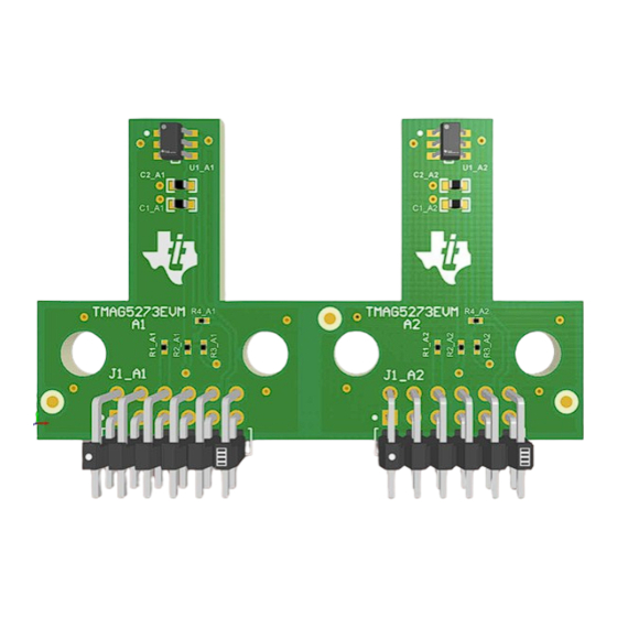
Figure 3-1. TMAG5x73 EVM With A1 and A2 Parts of Board Still Joined Together....................................................................
Figure 4-1. Sensor Control Board Connected to A1 Part of
Figure 4-3. Test Points Used to Enter DFU Mode Manually........................................................................................................
Figure 4-4. GUI Composer Application Window..........................................................................................................................
Figure 4-5. TI Cloud Agent..........................................................................................................................................................
Figure 4-6. Hardware Connected..............................................................................................................................................
Figure 4-7. Change Serial Port..................................................................................................................................................
Figure 4-8. Registers Page Icon................................................................................................................................................
Figure 4-9. Plots Page Icon.......................................................................................................................................................
Figure 4-10. Rotate & Push Module on EVM.............................................................................................................................
Figure 4-14. Device's Magnitude Plot........................................................................................................................................
Figure 4-15. Joystick Module on EVM.......................................................................................................................................
SLYU058C - MAY 2021 - REVISED SEPTEMBER 2022
Submit Document Feedback
ABSTRACT
Table of Contents
List of Figures
EVM................................................................................................7
EVM................................................................................................7
Page.......................................................................................................................................12
Plots...................................................................................................................................12
Plot.........................................................................................................................12
Copyright © 2022 Texas Instruments Incorporated
Table of Contents
17
17
18
24
30
10
10
10
10
13
13
TMAG5x73 Evaluation Modules
5
5
5
6
7
11
3
4
6
8
9
9
11
1
Advertisement
Table of Contents

Subscribe to Our Youtube Channel
Related Manuals for Texas Instruments TMAG5 73 Series


Summary of Contents for Texas Instruments TMAG5 73 Series
-
Page 1: Table Of Contents
EVM are synonymous with the TMAG5x73EVM. This document includes a schematic, reference printed circuit board (PCB) layouts, and a complete bill of materials (BOM). Table of Contents Overview....................................3 1.1 Kit Contents..................................5 1.2 Related Documentation From Texas Instruments......................2 Hardware....................................2.1 Features..................................... Operation....................................6 3.1 Quick Start Setup................................4 EVM Operation.................................. - Page 2 Google LLC. Firefox ® is a registered trademark of Mozilla Foundation. All trademarks are the property of their respective owners. TMAG5x73 Evaluation Modules SLYU058C – MAY 2021 – REVISED SEPTEMBER 2022 Submit Document Feedback Copyright © 2022 Texas Instruments Incorporated...
-
Page 3: Overview
Figure 1-1 shows the TMAG5273 EVM and Figure 1-2 shows the TMAG5173 EVM. Figure 1-1. TMAG5273 Evaluation Module SLYU058C – MAY 2021 – REVISED SEPTEMBER 2022 TMAG5x73 Evaluation Modules Submit Document Feedback Copyright © 2022 Texas Instruments Incorporated... -
Page 4: Figure 1-2. Tmag5173 Evaluation Module
Table 1-1. TMAG5x73 Device Summary PRODUCT SENSITIVITY RANGE OPTIONS TMAG5x73A1 ±40 mT, ±80 mT TMAG5x73A2 ±133 mT, ±266 mT TMAG5x73 Evaluation Modules SLYU058C – MAY 2021 – REVISED SEPTEMBER 2022 Submit Document Feedback Copyright © 2022 Texas Instruments Incorporated... -
Page 5: Kit Contents
Newer revisions are available from www.ti.com or the Texas Instruments' Literature Response Center at (800) 477-8924 or the Product Information Center at (972) 644-5580. When ordering, identify the document by both title and literature number. -
Page 6: Operation
7. Apply a magnetic field to the sensor by doing one of the following: a. Wave the included handheld magnet around the sensor. TMAG5x73 Evaluation Modules SLYU058C – MAY 2021 – REVISED SEPTEMBER 2022 Submit Document Feedback Copyright © 2022 Texas Instruments Incorporated... -
Page 7: Evm Operation
Figure 4-1. Sensor Control Board Connected to A1 Part of EVM Figure 4-2. Sensor Control Board Connected to A2 Part of EVM SLYU058C – MAY 2021 – REVISED SEPTEMBER 2022 TMAG5x73 Evaluation Modules Submit Document Feedback Copyright © 2022 Texas Instruments Incorporated... -
Page 8: Setup
Unplug the USB cable from the PC after the firmware is flashed, then plug the cable back in to reset the SCB. TMAG5x73 Evaluation Modules SLYU058C – MAY 2021 – REVISED SEPTEMBER 2022 Submit Document Feedback Copyright © 2022 Texas Instruments Incorporated... -
Page 9: Figure 4-4. Gui Composer Application Window
Figure 4-5. TI Cloud Agent 4. Click the icon in the GUI Composer window shown in Figure 4-4 to download the GUI offline (optional). SLYU058C – MAY 2021 – REVISED SEPTEMBER 2022 TMAG5x73 Evaluation Modules Submit Document Feedback Copyright © 2022 Texas Instruments Incorporated... -
Page 10: Figure 4-6. Hardware Connected
Click the SAVE PLOT button on the corresponding plot to save any specific plot. Figure 4-9. Plots Page Icon TMAG5x73 Evaluation Modules SLYU058C – MAY 2021 – REVISED SEPTEMBER 2022 Submit Document Feedback Copyright © 2022 Texas Instruments Incorporated... -
Page 11: Rotate And Push Demo
Set the Auto Read at the top of the register map to As fast as possible. 3. Go to the Rotate & Push tab inside the plots page (see Figure 4-11). SLYU058C – MAY 2021 – REVISED SEPTEMBER 2022 TMAG5x73 Evaluation Modules Submit Document Feedback Copyright © 2022 Texas Instruments Incorporated... -
Page 12: Figure 4-11. Rotate & Push Gui Page
4-13), and magnitude ( Figure 4-14) during this process. Figure 4-12. X and Y Channel GUI Plots Figure 4-13. Device's Angle Measurement Plot TMAG5x73 Evaluation Modules SLYU058C – MAY 2021 – REVISED SEPTEMBER 2022 Submit Document Feedback Copyright © 2022 Texas Instruments Incorporated... -
Page 13: Joystick Demo
TMAG5173 EVM parts. Figure 4-15. Joystick Module on EVM 2. In the GUI register page: SLYU058C – MAY 2021 – REVISED SEPTEMBER 2022 TMAG5x73 Evaluation Modules Submit Document Feedback Copyright © 2022 Texas Instruments Incorporated... -
Page 14: Figure 4-16. Gui Before Data Collection Begins With Joystick Module
When the user moves the joystick around, the X and Y readings change: Figure 4-17. Example X and Y Channel GUI Plots After Joystick Movement TMAG5x73 Evaluation Modules SLYU058C – MAY 2021 – REVISED SEPTEMBER 2022 Submit Document Feedback Copyright © 2022 Texas Instruments Incorporated... -
Page 15: Direct Evm Serial Communication
Figure 4-19 is an example response to this command: Figure 4-19. Example Register Write Response Other useful commands include the following: SLYU058C – MAY 2021 – REVISED SEPTEMBER 2022 TMAG5x73 Evaluation Modules Submit Document Feedback Copyright © 2022 Texas Instruments Incorporated... -
Page 16: Figure 4-20. Example Firmware Revision Command
– If the device is in standby mode and new conversions are set to be triggered through I2C, doing a register read at register 0 automatically starts a new set of conversions. TMAG5x73 Evaluation Modules SLYU058C – MAY 2021 – REVISED SEPTEMBER 2022 Submit Document Feedback Copyright © 2022 Texas Instruments Incorporated... -
Page 17: Circuitry
DFU mode. If the EVM enters DFU mode, whether through software or hardware, this LED is turned off while the LED D5 remains on. SLYU058C – MAY 2021 – REVISED SEPTEMBER 2022 TMAG5x73 Evaluation Modules Submit Document Feedback Copyright © 2022 Texas Instruments Incorporated... -
Page 18: Schematics, Pcb Layout, And Bill Of Materials
J1_A1B J1_A1A +3V3 NRPN062PARN-RC NRPN062PARN-RC LOGO LOGO Texas Instruments CE Mark WEEE logo Figure 6-1. TMAG5273A1 Part of EVM Schematic TMAG5x73 Evaluation Modules SLYU058C – MAY 2021 – REVISED SEPTEMBER 2022 Submit Document Feedback Copyright © 2022 Texas Instruments Incorporated... -
Page 19: Figure 6-2. Tmag5273A2 Part Of Evm Schematic
J1_A2B J1_A2A +3V3 NRPN062PARN-RC NRPN062PARN-RC LOGO LOGO Texas Instruments CE Mark WEEE logo Figure 6-2. TMAG5273A2 Part of EVM Schematic SLYU058C – MAY 2021 – REVISED SEPTEMBER 2022 TMAG5x73 Evaluation Modules Submit Document Feedback Copyright © 2022 Texas Instruments Incorporated... -
Page 20: Figure 6-3. Tmag5273Evm Hardware Schematic
The boards should be shipped connected together. Please do not break the board into two by cutting on the score line. Figure 6-3. TMAG5273EVM Hardware Schematic TMAG5x73 Evaluation Modules SLYU058C – MAY 2021 – REVISED SEPTEMBER 2022 Submit Document Feedback Copyright © 2022 Texas Instruments Incorporated... -
Page 21: Figure 6-4. Tmag5173A1 Part Of Evm Schematic
J1_A1A +3V3 R1_A1 NRPN062PARN-RC NRPN062PARN-RC LOGO LOGO Texas Instruments CE Mark WEEE logo Figure 6-4. TMAG5173A1 Part of EVM Schematic SLYU058C – MAY 2021 – REVISED SEPTEMBER 2022 TMAG5x73 Evaluation Modules Submit Document Feedback Copyright © 2022 Texas Instruments Incorporated... -
Page 22: Figure 6-5. Tmag5173A2 Part Of Evm Schematic
J1_A2A +3V3 R1_A2 NRPN062PARN-RC NRPN062PARN-RC LOGO LOGO Texas Instruments CE Mark WEEE logo Figure 6-5. TMAG5173A2 Part of EVM Schematic TMAG5x73 Evaluation Modules SLYU058C – MAY 2021 – REVISED SEPTEMBER 2022 Submit Document Feedback Copyright © 2022 Texas Instruments Incorporated... -
Page 23: Figure 6-6. Tmag5173Evm Hardware Schematic
The boards should be shipped connected together. Please do not break the board into two by cutting on the score line. Figure 6-6. TMAG5173EVM Hardware Schematic SLYU058C – MAY 2021 – REVISED SEPTEMBER 2022 TMAG5x73 Evaluation Modules Submit Document Feedback Copyright © 2022 Texas Instruments Incorporated... -
Page 24: Pcb Layout
Schematics, PCB Layout, and Bill of Materials www.ti.com 6.2 PCB Layout Figure 6-7. TMAG5273EVM Top View Figure 6-8. TMAG5273EVM Top Layer TMAG5x73 Evaluation Modules SLYU058C – MAY 2021 – REVISED SEPTEMBER 2022 Submit Document Feedback Copyright © 2022 Texas Instruments Incorporated... -
Page 25: Figure 6-9. Tmag5273Evm Bottom View
Schematics, PCB Layout, and Bill of Materials Figure 6-9. TMAG5273EVM Bottom View Figure 6-10. TMAG5273EVM Bottom Layer SLYU058C – MAY 2021 – REVISED SEPTEMBER 2022 TMAG5x73 Evaluation Modules Submit Document Feedback Copyright © 2022 Texas Instruments Incorporated... -
Page 26: Figure 6-11. Tmag5173Evm Top View
Schematics, PCB Layout, and Bill of Materials www.ti.com Figure 6-11. TMAG5173EVM Top View Figure 6-12. TMAG5173EVM Top Layer TMAG5x73 Evaluation Modules SLYU058C – MAY 2021 – REVISED SEPTEMBER 2022 Submit Document Feedback Copyright © 2022 Texas Instruments Incorporated... -
Page 27: Figure 6-13. Tmag5173Evm Bottom View
Schematics, PCB Layout, and Bill of Materials Figure 6-13. TMAG5173EVM Bottom View Figure 6-14. TMAG5173EVM Bottom Layer SLYU058C – MAY 2021 – REVISED SEPTEMBER 2022 TMAG5x73 Evaluation Modules Submit Document Feedback Copyright © 2022 Texas Instruments Incorporated... -
Page 28: Bill Of Materials
3-Axis Linear Hall-Effect Sensor with I2C SOT23-6 TMAG5273A1QDBVR Texas Instruments Interface Texas Instruments U1_A2 3-Axis Linear Hall Effect Sensor With I2C SOT-23-6 TMAG5273A2QDBVR Interface TMAG5x73 Evaluation Modules SLYU058C – MAY 2021 – REVISED SEPTEMBER 2022 Submit Document Feedback Copyright © 2022 Texas Instruments Incorporated... -
Page 29: Table 6-2. Tmag5173Evm Bill Of Materials
TMAG5173A1QDBVRQ1 Texas Instruments Hall-Effect Sensor With I2C Interface U1_A2 Low-Power Linear 3D SOT23-6 TMAG5173A2QDBVRQ1 Texas Instruments Hall-Effect Sensor With I2C Interface SLYU058C – MAY 2021 – REVISED SEPTEMBER 2022 TMAG5x73 Evaluation Modules Submit Document Feedback Copyright © 2022 Texas Instruments Incorporated... -
Page 30: Revision History
Added Section 4.4 ............................• Changed the figures in Section 6.1 ........................18 • Changed the figures in Section 6.2 ........................24 TMAG5x73 Evaluation Modules SLYU058C – MAY 2021 – REVISED SEPTEMBER 2022 Submit Document Feedback Copyright © 2022 Texas Instruments Incorporated... - Page 31 STANDARD TERMS FOR EVALUATION MODULES Delivery: TI delivers TI evaluation boards, kits, or modules, including any accompanying demonstration software, components, and/or documentation which may be provided together or separately (collectively, an “EVM” or “EVMs”) to the User (“User”) in accordance with the terms set forth herein.
- Page 32 www.ti.com Regulatory Notices: 3.1 United States 3.1.1 Notice applicable to EVMs not FCC-Approved: FCC NOTICE: This kit is designed to allow product developers to evaluate electronic components, circuitry, or software associated with the kit to determine whether to incorporate such items in a finished product and software developers to write software applications for use with the end product.
- Page 33 www.ti.com Concernant les EVMs avec antennes détachables Conformément à la réglementation d'Industrie Canada, le présent émetteur radio peut fonctionner avec une antenne d'un type et d'un gain maximal (ou inférieur) approuvé pour l'émetteur par Industrie Canada. Dans le but de réduire les risques de brouillage radioélectrique à...
- Page 34 www.ti.com EVM Use Restrictions and Warnings: 4.1 EVMS ARE NOT FOR USE IN FUNCTIONAL SAFETY AND/OR SAFETY CRITICAL EVALUATIONS, INCLUDING BUT NOT LIMITED TO EVALUATIONS OF LIFE SUPPORT APPLICATIONS. 4.2 User must read and apply the user guide and other available documentation provided by TI regarding the EVM prior to handling or using the EVM, including without limitation any warning or restriction notices.
- Page 35 Notwithstanding the foregoing, any judgment may be enforced in any United States or foreign court, and TI may seek injunctive relief in any United States or foreign court. Mailing Address: Texas Instruments, Post Office Box 655303, Dallas, Texas 75265 Copyright © 2019, Texas Instruments Incorporated...
- Page 36 TI products. TI’s provision of these resources does not expand or otherwise alter TI’s applicable warranties or warranty disclaimers for TI products. TI objects to and rejects any additional or different terms you may have proposed. IMPORTANT NOTICE Mailing Address: Texas Instruments, Post Office Box 655303, Dallas, Texas 75265 Copyright © 2022, Texas Instruments Incorporated...
Need help?
Do you have a question about the TMAG5 73 Series and is the answer not in the manual?
Questions and answers