Table of Contents
Advertisement
Quick Links
www.ti.com
EVM User's Guide: TMUXS7614DEVM
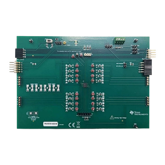
TMUXS7614D Evaluation Module
Description
The TMUXS7614DEVM is used to evaluate the
performance of the TMUXS7614D. The evaluation
module (EVM) comes with the TMUXS7614D device
soldered on. The EVM allows for engineers to easily
evaluate the TMUXS7614D for applications, such
as test and measurement. The TMUXS7614DEVM
connects to a
USB2ANY
separately on ti.com) through the SPI_L_Connect
header. Users can choose to use an SPI with this
header if desired. Headers are also provided for
each of the source and drain pins. Multiple terminals
provide power to the device with an option for the user
TMUXS7614DEVM (Top View)
SCDU039 – MAY 2024
Submit Document Feedback
controller (ordered
Copyright © 2024 Texas Instruments Incorporated
to provide a defined digital logic supply voltage. The
digital logic supply voltage can be supplied from the
USB2ANY as well.
Features
•
TMUXS7614D pre-soldered on board
•
16 test points on I/Os
•
Four SMB connectors
•
LED indicator for VL supply
•
Reset button
•
External PC control in tandem with TI evaluation
software
•
SPI GUI
TMUXS7614DEVM (Bottom View)
Description
TMUXS7614D Evaluation Module
1
Advertisement
Table of Contents

Subscribe to Our Youtube Channel
Related Manuals for Texas Instruments TMUXS7614D


Summary of Contents for Texas Instruments TMUXS7614D
- Page 1 The TMUXS7614DEVM is used to evaluate the USB2ANY as well. performance of the TMUXS7614D. The evaluation module (EVM) comes with the TMUXS7614D device Features soldered on. The EVM allows for engineers to easily •...
-
Page 2: Kit Contents
The SPI also supports daisy chain mode. Coupled with the flow through routing of the SPI pins, this allows for increased channel density in the system. The TMUXS7614D is a part of the precision switches and multiplexers family of devices and have very low on and off leakage currents allowing them to be used in high precision measurement applications. -
Page 3: Push Buttons
2.3 Push Buttons The TMUXS7614D EVM provides a physical hardware reset button labeled Reset. Note that Revision 1 of the board only allows for the reset button to be utilized in a single EVM mode. Revision 2 allows for use of this hardware reset button in daisy chain mode. - Page 4 From the Home tab, the user can go into Daisy Chain and Registers tabs. The Info, Setup, and Data tabs are currently not operational and will be implemented in a future revision. TMUXS7614D Evaluation Module SCDU039 – MAY 2024 Submit Document Feedback Copyright © 2024 Texas Instruments Incorporated...
- Page 5 The select bar can select a number of devices to control on the daisy chain. d. To send signals to the devices on the daisy chain, click on the checkboxes correlated to the switch of the device. Figure 3-3. TMUXS7614D-SPI-EVM GUI Daisy Chain Mode Tab SCDU039 – MAY 2024 TMUXS7614D Evaluation Module Submit Document Feedback Copyright ©...
- Page 6 When autoread and autowrite are disabled, the user has to press those buttons manually when users want to either write or read. Figure 3-4. TMUXS7614D-SPI-EVM GUI Register Map Tab TMUXS7614D Evaluation Module SCDU039 – MAY 2024 Submit Document Feedback Copyright ©...
- Page 7 5011 5011 5011 HTSW-103-09-G-S SDI/O 5010 GND I/O /RESET/VL /CS I/O 100k Thermal_ Pad 100nF TMUXS7614DZEMR /RES ET/VL Figure 4-1. TMUXS7614DEVM Schematic Page 1 SCDU039 – MAY 2024 TMUXS7614D Evaluation Module Submit Document Feedback Copyright © 2024 Texas Instruments Incorporated...
- Page 8 KPTL-3216CGCK-01 Green LED_FET 1000 R_FET /RESET/V L Reset /RESET/VL EVQ-5PN04K 100k 100k EXT_RESET SI2342DS-T1-GE3 5014 EXT_RESET 10129378-903001BLF TMUX1219DCKR Figure 4-2. TMUXS7614DEVM Schematic Page 2 TMUXS7614D Evaluation Module SCDU039 – MAY 2024 Submit Document Feedback Copyright © 2024 Texas Instruments Incorporated...
-
Page 9: Pcb Layouts
Hardware Design Files 4.2 PCB Layouts Figure 4-3. TMUXS7614DEVM Top Layer Layout Figure 4-4. TMUXS7614DEVM Power Layer Layout SCDU039 – MAY 2024 TMUXS7614D Evaluation Module Submit Document Feedback Copyright © 2024 Texas Instruments Incorporated... - Page 10 Hardware Design Files www.ti.com Figure 4-5. TMUXS7614DEVM Ground Layer Layout Figure 4-6. TMUXS7614DEVM Bottom Layer Layout TMUXS7614D Evaluation Module SCDU039 – MAY 2024 Submit Document Feedback Copyright © 2024 Texas Instruments Incorporated...
-
Page 11: Bill Of Materials (Bom)
Panasonic 0.05A, 12 VDC, SMD SPI_L_Connect1 Header, 100mil, 5x2, R/A, Gold, TH 68021-210HLF Receptacle, 2.54mm, 5x2, Gold, Sullins Connector SPI_R_Connect1 SFH11-PBPC-D05-RA-BK R/A, TH Solutions SCDU039 – MAY 2024 TMUXS7614D Evaluation Module Submit Document Feedback Copyright © 2024 Texas Instruments Incorporated... -
Page 12: Additional Information
Apple Inc. ® Internet Explorer is a registered trademark of Microsoft Corporation. All trademarks are the property of their respective owners. TMUXS7614D Evaluation Module SCDU039 – MAY 2024 Submit Document Feedback Copyright © 2024 Texas Instruments Incorporated... -
Page 13: Important Notice
TI products. TI’s provision of these resources does not expand or otherwise alter TI’s applicable warranties or warranty disclaimers for TI products. TI objects to and rejects any additional or different terms you may have proposed. IMPORTANT NOTICE Mailing Address: Texas Instruments, Post Office Box 655303, Dallas, Texas 75265 Copyright © 2024, Texas Instruments Incorporated...
Need help?
Do you have a question about the TMUXS7614D and is the answer not in the manual?
Questions and answers