Advertisement
www.ti.com
EVM User's Guide: TMUX10DGSEVM
TMUX10DGS Evaluation Module
Description
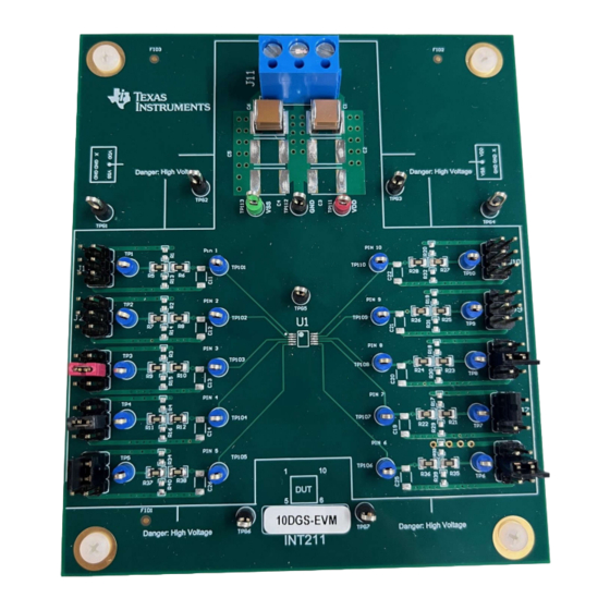
The TMUX10DGSEVM is used to evaluate the
performance of the 10 pin DGS package. The
evaluation module (EVM) comes with a pad to allow
10 pin DGS devices to be soldered on. Additionally,
test points on board are provided to allow for the
flexibility to test for various signals.
Features
•
One power supply decoupling capacitor from VDD
to ground (3.3µF, 6mm × 5mm)
•
Two additional power supply decoupling capacitor
pads from VDD to ground (6mm × 5mm)
•
One power supply decoupling capacitor from VSS
to ground (3.3µF, 6mm × 5mm)
•
Two additional power supply decoupling capacitor
pads from VSS to ground (6mm × 5mm)
•
Pads available near VDD and VSS input for TVS
Diodes ( L × W: 8.13mm × 6.22mm)
TMUX10DGSEVM (Front Side)
SCDU038 – APRIL 2024
Submit Document Feedback
•
One pad for switches and multiplexers in the 10-
pin DGS package
•
10 generic 6-pin headers for power, analog or
digital signals being switched, and control signals
•
All 10 generic signal pathways have 2 0805 size
0Ω resistors installed between IC pad and header
•
All 10 generic signal pathways have 0603 sized
pads to add a pull-up, pull-down, or resistive load
to the signal pathway
•
All 10 generic signal pathways contain an 1812
sized pad to add a capacitive load to the signal
pathway
•
All 10 generic signal pathways contain a 1206
sized pad to add a capacitive load to the signal
pathway
•
One common 3-port terminal block for GND, VDD,
and VSS power signals
Copyright © 2024 Texas Instruments Incorporated
TMUX10DGSEVM (Back Side)
TMUX10DGS Evaluation Module
Description
1
Advertisement
Table of Contents

Related Manuals for Texas Instruments TMUX10DGSEVM


Summary of Contents for Texas Instruments TMUX10DGSEVM
- Page 1 • One pad for switches and multiplexers in the 10- Description pin DGS package The TMUX10DGSEVM is used to evaluate the • 10 generic 6-pin headers for power, analog or performance of the 10 pin DGS package. The digital signals being switched, and control signals evaluation module (EVM) comes with a pad to allow •...
-
Page 2: Kit Contents
1.3 Specification The TMUX10DGSEVM is used for quick prototyping of TI's Analog Switches and Multiplexers in 10 pin DGS packages. The EVM has two test points on each I/O for a total of twenty total test points to support testing of 10DGS packages. - Page 3 2.1 Power Requirements TMUX10DGSEVM requires a supply provided either through the J11 terminal, or directly hooked to the red VDD test point to provide a passive signal pathway between the Sx and Dx pins in according to the logic selected.
-
Page 4: Jumper Information
In cases where the tests requires pull-up or pull-down resistors versus directly attaching the source to the respective U1 pin, all 8 generic pathways contain 0603 resistor pads to add these components. Table 2-2 shows the IDs. TMUX10DGS Evaluation Module SCDU038 – APRIL 2024 Submit Document Feedback Copyright © 2024 Texas Instruments Incorporated... - Page 5 The 1812 sized capacitor pads are on the bottom side of the EVM. Table 2-3. RC Load Configuration Map Jumper ID 0603 Sized Resistor Pad ID 1206 Sized Capacitor Pad ID 1812 Sized Capacitor Pad ID SCDU038 – APRIL 2024 TMUX10DGS Evaluation Module Submit Document Feedback Copyright © 2024 Texas Instruments Incorporated...
-
Page 6: Test Points
Test Point ID Color Signal TP111 TP112 Black TP113 Green Black TPG1 Black TPG2 Black TPG3 Black TPG4 Black TPG5 Black TPG6 Black TPG7 TMUX10DGS Evaluation Module SCDU038 – APRIL 2024 Submit Document Feedback Copyright © 2024 Texas Instruments Incorporated... - Page 7 Hardware Design Files 3 Hardware Design Files 3.1 Schematics Figure 3-1. Main Schematic – TMUX10DGS All Components Shown Figure 3-2. Main Schematic – TMUX10DGS Default SCDU038 – APRIL 2024 TMUX10DGS Evaluation Module Submit Document Feedback Copyright © 2024 Texas Instruments Incorporated...
-
Page 8: Pcb Layouts
Hardware Design Files www.ti.com 3.2 PCB Layouts Figure 3-3. TMUX10DGSEVM Top Layer Layout TMUX10DGS Evaluation Module SCDU038 – APRIL 2024 Submit Document Feedback Copyright © 2024 Texas Instruments Incorporated... - Page 9 Hardware Design Files Figure 3-4. TMUX10DGSEVM Bottom Layer Layout SCDU038 – APRIL 2024 TMUX10DGS Evaluation Module Submit Document Feedback Copyright © 2024 Texas Instruments Incorporated...
- Page 10 TPG3, TPG4, TPG5, Test Point, Multipurpose, Black, TH 5011 Keystone point TPG6, TPG7 Green Multipurpose Test TP113 Test Point, Multipurpose, Green, TH 5126 Keystone point TMUX10DGS Evaluation Module SCDU038 – APRIL 2024 Submit Document Feedback Copyright © 2024 Texas Instruments Incorporated...
- Page 11 R30, R31, R32, R33, R34, R39, R40 44V, Low-RON, 1:1 (SPST), 2-Channel Precision Switches with Latch-Up Immunity and VSSOP10 PTMUX7221DGSR Texas Instruments 1.8V Logic SCDU038 – APRIL 2024 TMUX10DGS Evaluation Module Submit Document Feedback Copyright © 2024 Texas Instruments Incorporated...
-
Page 12: Additional Information
Additional Information www.ti.com 4 Additional Information 4.1 Trademarks All trademarks are the property of their respective owners. TMUX10DGS Evaluation Module SCDU038 – APRIL 2024 Submit Document Feedback Copyright © 2024 Texas Instruments Incorporated... - Page 13 STANDARD TERMS FOR EVALUATION MODULES Delivery: TI delivers TI evaluation boards, kits, or modules, including any accompanying demonstration software, components, and/or documentation which may be provided together or separately (collectively, an “EVM” or “EVMs”) to the User (“User”) in accordance with the terms set forth herein.
- Page 14 www.ti.com Regulatory Notices: 3.1 United States 3.1.1 Notice applicable to EVMs not FCC-Approved: FCC NOTICE: This kit is designed to allow product developers to evaluate electronic components, circuitry, or software associated with the kit to determine whether to incorporate such items in a finished product and software developers to write software applications for use with the end product.
- Page 15 www.ti.com Concernant les EVMs avec antennes détachables Conformément à la réglementation d'Industrie Canada, le présent émetteur radio peut fonctionner avec une antenne d'un type et d'un gain maximal (ou inférieur) approuvé pour l'émetteur par Industrie Canada. Dans le but de réduire les risques de brouillage radioélectrique à...
- Page 16 www.ti.com EVM Use Restrictions and Warnings: 4.1 EVMS ARE NOT FOR USE IN FUNCTIONAL SAFETY AND/OR SAFETY CRITICAL EVALUATIONS, INCLUDING BUT NOT LIMITED TO EVALUATIONS OF LIFE SUPPORT APPLICATIONS. 4.2 User must read and apply the user guide and other available documentation provided by TI regarding the EVM prior to handling or using the EVM, including without limitation any warning or restriction notices.
- Page 17 Notwithstanding the foregoing, any judgment may be enforced in any United States or foreign court, and TI may seek injunctive relief in any United States or foreign court. Mailing Address: Texas Instruments, Post Office Box 655303, Dallas, Texas 75265 Copyright © 2023, Texas Instruments Incorporated...
-
Page 18: Important Notice
TI products. TI’s provision of these resources does not expand or otherwise alter TI’s applicable warranties or warranty disclaimers for TI products. TI objects to and rejects any additional or different terms you may have proposed. IMPORTANT NOTICE Mailing Address: Texas Instruments, Post Office Box 655303, Dallas, Texas 75265 Copyright © 2024, Texas Instruments Incorporated...
Need help?
Do you have a question about the TMUX10DGSEVM and is the answer not in the manual?
Questions and answers