Table of Contents
Advertisement
Quick Links
www.ti.com
User's Guide
TMUX72XXDGKEVM Evaluation Module
This user's guide describes the characteristics, operation, and use of the TMUX72XXDGKEVM Evaluation
Module (EVM). A complete schematic diagram, printed-circuit board layouts, and bill of materials are included in
this document.
1
Introduction.............................................................................................................................................................................2
EVM..........................................................................................................................................................2
Images.......................................................................................................................................................................3
2 EVM Setup...............................................................................................................................................................................
3.1
Connectors.........................................................................................................................................................................6
Points..........................................................................................................................................................................6
Layouts............................................................................................................................................................................7
5
Schematics..............................................................................................................................................................................9
Materials......................................................................................................................................................................11
Figure 4-1. Top View Illustration of the TMUX72XXDGKEVM Layout.........................................................................................
Table 2-1. Component Pad to TMUX72XX Pin Matrix.................................................................................................................
Table 2-2. TMUX7219 Truth Table...............................................................................................................................................
Table 3-2. Test Point Signal Connections....................................................................................................................................
Table 6-1. TMUX72XXDGKEVM Bill of Materials......................................................................................................................
Trademarks
All trademarks are the property of their respective owners.
SCDU021 - DECEMBER 2020
Submit Document Feedback
ABSTRACT
Table of Contents
Warnings.........................................................................................................................2
Points..........................................................................................................................................6
List of Figures
View..........................................................................................................................3
View...........................................................................................................................4
Designator..................................................................................................5
View)................................................................................................10
List of Tables
Functions.......................................................................................................................6
Copyright © 2020 Texas Instruments Incorporated
Layout....................................................................................8
View)...............................................................................................9
Table of Contents
TMUX72XXDGKEVM Evaluation Module
5
7
5
5
6
11
1
Advertisement
Table of Contents

Subscribe to Our Youtube Channel
Related Manuals for Texas Instruments TMUX72XXDGKEVM


Summary of Contents for Texas Instruments TMUX72XXDGKEVM
-
Page 1: Table Of Contents
User’s Guide TMUX72XXDGKEVM Evaluation Module ABSTRACT This user's guide describes the characteristics, operation, and use of the TMUX72XXDGKEVM Evaluation Module (EVM). A complete schematic diagram, printed-circuit board layouts, and bill of materials are included in this document. Table of Contents Introduction.....................................2... -
Page 2: Introduction
1 Introduction The TMUX72XXDGKEVM supports evaluation of the TMUX72XX devices in the 8-pin VSSOP (DGK) package, including TMUX7219DGK. TMUX7219 is a complementary metal-oxide semiconductor (CMOS) switch with latch-up immunity in a single channel, 2:1 (SPDT) configuration. The device works well with dual supplies (±4.5 V to ±22 V), a single supply (4.5 V to 44 V), or asymmetric supplies (such as V... -
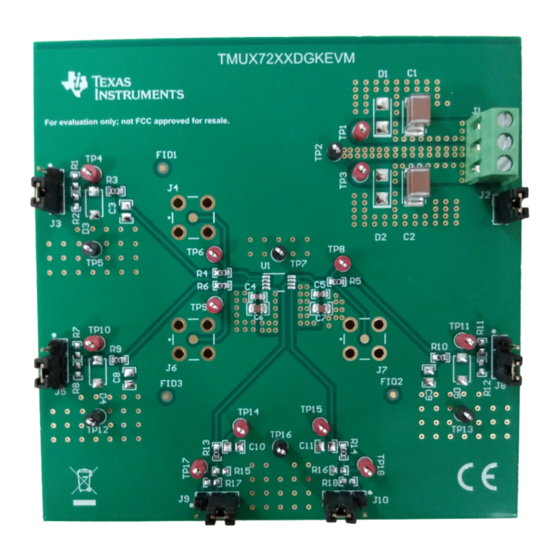
Page 3: Evm Images
Introduction 1.3 EVM Images Figure 1-1. TMUX72XXDGKEVM Topside View SCDU021 – DECEMBER 2020 TMUX72XXDGKEVM Evaluation Module Submit Document Feedback Copyright © 2020 Texas Instruments Incorporated... -
Page 4: Figure 1-2. Tmux72Xxdgkevm Bottom View
Introduction www.ti.com Figure 1-2. TMUX72XXDGKEVM Bottom View TMUX72XXDGKEVM Evaluation Module SCDU021 – DECEMBER 2020 Submit Document Feedback Copyright © 2020 Texas Instruments Incorporated... -
Page 5: Evm Setup
Figure 2-1. Generic Jumper and Header Position 1 Designator Table 2-2 is the truth table for the TMUX72XXDGKEVM compatible device, TMUX7219, for reference to configure the corresponding control jumpers. Additional signal path jumpers may be configured as shown in Table 3-1. -
Page 6: Evm Connectors And Test Points
I/O signal path 1 TP4 and TP6 I/O signal path 2 TP8 and TP11 I/O signal path 3 TP9 and TP10 TP14 and TP17 TP15 and TP18 TMUX72XXDGKEVM Evaluation Module SCDU021 – DECEMBER 2020 Submit Document Feedback Copyright © 2020 Texas Instruments Incorporated... -
Page 7: Pcb Layouts
PCB Layouts 4 PCB Layouts Figure 4-1 Figure 4-2 show the EVM PCB layout images. Figure 4-1. Top View Illustration of the TMUX72XXDGKEVM Layout SCDU021 – DECEMBER 2020 TMUX72XXDGKEVM Evaluation Module Submit Document Feedback Copyright © 2020 Texas Instruments Incorporated... -
Page 8: Figure 4-2. Bottom View Illustration Of The Tmux72Xxdgkevm
PCB Layouts www.ti.com Figure 4-2. Bottom View Illustration of the TMUX72XXDGKEVM Layout TMUX72XXDGKEVM Evaluation Module SCDU021 – DECEMBER 2020 Submit Document Feedback Copyright © 2020 Texas Instruments Incorporated... -
Page 9: Schematics
DNI. Figure 5-2 shows the DNI view after removing the DNI parts which are not included on the out-of-the-box evaluation module. Figure 5-1. Schematic of the TMUX72XXDGKEVM (Editor View) SCDU021 – DECEMBER 2020 TMUX72XXDGKEVM Evaluation Module Submit Document Feedback Copyright ©... -
Page 10: Figure 5-2. Schematic Of The Tmux72Xxdgkevm
Schematics www.ti.com Figure 5-2. Schematic of the TMUX72XXDGKEVM (DNI View) TMUX72XXDGKEVM Evaluation Module SCDU021 – DECEMBER 2020 Submit Document Feedback Copyright © 2020 Texas Instruments Incorporated... -
Page 11: Bill Of Materials
Schematics 6 Bill of Materials Table 6-1 details the EVM bill of materials. Table 6-1. TMUX72XXDGKEVM Bill of Materials Designator Component Manufactuer Description Quantity C1, C2 CKG45NX7S2A106M500JJ CAP, CERM, 10 µF, 100 V, ± 20%, X7S, AEC-Q200 Grade 1, 1812... - Page 12 STANDARD TERMS FOR EVALUATION MODULES Delivery: TI delivers TI evaluation boards, kits, or modules, including any accompanying demonstration software, components, and/or documentation which may be provided together or separately (collectively, an “EVM” or “EVMs”) to the User (“User”) in accordance with the terms set forth herein.
- Page 13 www.ti.com Regulatory Notices: 3.1 United States 3.1.1 Notice applicable to EVMs not FCC-Approved: FCC NOTICE: This kit is designed to allow product developers to evaluate electronic components, circuitry, or software associated with the kit to determine whether to incorporate such items in a finished product and software developers to write software applications for use with the end product.
- Page 14 www.ti.com Concernant les EVMs avec antennes détachables Conformément à la réglementation d'Industrie Canada, le présent émetteur radio peut fonctionner avec une antenne d'un type et d'un gain maximal (ou inférieur) approuvé pour l'émetteur par Industrie Canada. Dans le but de réduire les risques de brouillage radioélectrique à...
- Page 15 www.ti.com EVM Use Restrictions and Warnings: 4.1 EVMS ARE NOT FOR USE IN FUNCTIONAL SAFETY AND/OR SAFETY CRITICAL EVALUATIONS, INCLUDING BUT NOT LIMITED TO EVALUATIONS OF LIFE SUPPORT APPLICATIONS. 4.2 User must read and apply the user guide and other available documentation provided by TI regarding the EVM prior to handling or using the EVM, including without limitation any warning or restriction notices.
- Page 16 Notwithstanding the foregoing, any judgment may be enforced in any United States or foreign court, and TI may seek injunctive relief in any United States or foreign court. Mailing Address: Texas Instruments, Post Office Box 655303, Dallas, Texas 75265 Copyright © 2019, Texas Instruments Incorporated...
- Page 17 TI products. TI’s provision of these resources does not expand or otherwise alter TI’s applicable warranties or warranty disclaimers for TI products.IMPORTANT NOTICE Mailing Address: Texas Instruments, Post Office Box 655303, Dallas, Texas 75265 Copyright © 2021, Texas Instruments Incorporated...
- Page 18 Mouser Electronics Authorized Distributor Click to View Pricing, Inventory, Delivery & Lifecycle Information: Texas Instruments TMUX72XXDGKEVM...
Need help?
Do you have a question about the TMUX72XXDGKEVM and is the answer not in the manual?
Questions and answers