Table of Contents
Advertisement
Quick Links
IMPORTANT SAFETY INFORMATION:
Read this manual first before attempting to install or use this electric fireplace. Always comply with the
warnings and safety instructions contained in this manual to prevent personal injury or property damage.
Service Manual
Models
E-SLIM LINEAR 1200/450 I
E-SLIM LINEAR 1700/450 I
E-SLIM LINEAR 2200/450 I
40012202-2306
Advertisement
Table of Contents

Related Manuals for Faber E-SLIM LINEAR 1200/450 I


Summary of Contents for Faber E-SLIM LINEAR 1200/450 I
- Page 1 Service Manual Models E-SLIM LINEAR 1200/450 I E-SLIM LINEAR 1700/450 I E-SLIM LINEAR 2200/450 I IMPORTANT SAFETY INFORMATION: Read this manual first before attempting to install or use this electric fireplace. Always comply with the warnings and safety instructions contained in this manual to prevent personal injury or property damage.
-
Page 2: Table Of Contents
Table of Contents Exploded Parts Diagrams . . . . . . . . . . . . . . . . . . . . . . . . . . . . . . . . . . . . . . . . . . . . . . . . . . . . . . 3 E-SLIM LINEAR 1200/450 l Replacement Parts List . -
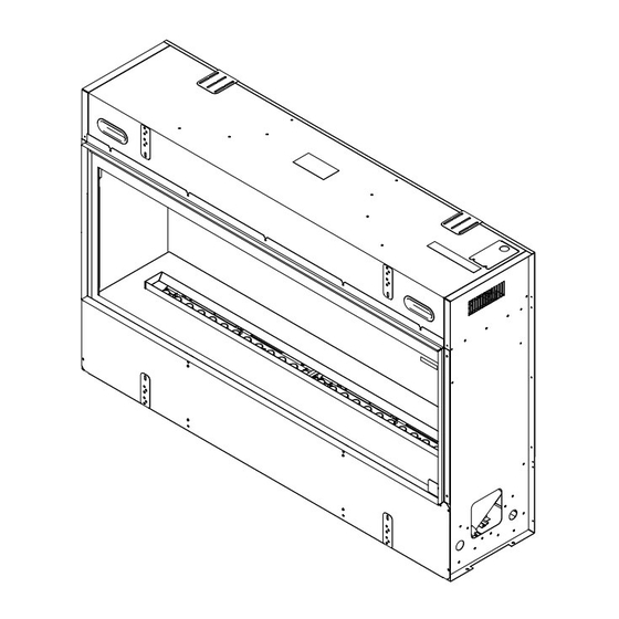
Page 3: Exploded Parts Diagrams
Exploded Parts Diagrams Module (2) Reference page 6 for the module replacement parts list . E-SLIM LINEAR 1200/450 l 1. Remote Control ....03.08.002.112 13. -
Page 4: Exploded Parts Diagrams
Exploded Parts Diagrams Module (3) Reference page 6 for the module replacement parts list . E-SLIM LINEAR 1700/450 l 13. Module Wire Harness Set ..X-9602790100RP 1. Remote Control ....03.08.002.112 14. -
Page 5: Exploded Parts Diagrams
Exploded Parts Diagrams 22 23 Module (4) Reference page 6 for the module replacement parts list . E-SLIM LINEAR 2200/450 l 13. Module Wire Harness Set ..X-9602790100RP 1. Remote Control ....03.08.002.112 14. -
Page 6: Exploded Parts Diagrams
Exploded Parts Diagrams Model Number of Module Modules E-SLIM LINEAR 1200/450 l E-SLIM LINEAR 1700/450 l E-SLIM LINEAR 2200/450 l Module Replacement Parts List 11. Heating Element ..... . 06023619 1. -
Page 7: Wiring Diagrams
Wiring Diagrams Module A secondary transducer is optional. Only one transducer is needed for operation. -
Page 8: Wiring And Plumbing Diagram
Wiring and Plumbing Diagram E-SLIM LINEAR 1200/450 l Firebox Wiring Diagram Plumbing Diagram To Module To Module... -
Page 9: Wiring And Plumbing Diagrams
Wiring and Plumbing Diagrams E-SLIM LINEAR 1700/450 l Firebox Wiring Diagram Plumbing Diagram To Module To Module To Module... -
Page 10: Wiring And Plumbing Diagrams
Wiring and Plumbing Diagrams E-SLIM LINEAR 2200/450 l Firebox Wiring Diagram Plumbing Diagram To Module To Module To Module To Module... -
Page 11: Replacement Part Procedures
Replacement Part Procedures Preparing for Service WARNING: If the firebox was operating prior to servicing, allow at least 10 minutes for the heating elements to cool off to avoid accidental burning of skin. WARNING: Disconnect power before attempting any maintenance to reduce the risk of electric shock or injury to persons. -
Page 12: Heater Assembly Replacement
Replacement Part Procedures Heater Assembly Replacement Tools Required: Phillips-Head Screwdriver 1. Follow instructions for preparing for service. (Page 11) 2. Remove the 4 screws that secure the heater assembly panel (middle panel). Carefully lower the heater assembly. (Figure 3) NOTE: The heater assembly is supported by hooks in the back. 3. -
Page 13: Extractor Fan Replacement
Replacement Part Procedures Extractor Fan Replacement Tools Required: Phillips-Head Screwdriver 1. Follow instructions for preparing for service. (Page 11) 2. Remove the 2 screws on the air deflector (Figure 6). NOTE: The side panel is supported by hooks in the back. 3. -
Page 14: Main Control Board Replacement
Replacement Part Procedures Main Control Board Replacement Tools Required: Phillips-Head Screwdriver 1. Follow instructions for preparing for service. (Page 11) 2. Remove the 7 screws that secure the top panel furthest to the right. As it drops it will be hung on the back posts. 3. -
Page 15: Hidden Touch Controls/Housing Replacement
Replacement Part Procedures Hidden Touch Controls/Housing Replacement NOTE: A new QR code sticker comes with the new Hidden Touch Control. The unit will need to be resynced with the app if applicable. Tools Required: Phillips-Head Screwdriver 1. Follow the instructions for preparing for service. (Page 11) 2. -
Page 16: Power Adaptor Replacement
Replacement Part Procedures Power Adaptor Replacement Tools Required: Phillips-Head Screwdriver, Pliers 1. Follow the instructions for preparing for service. (Page 11) NOTE: The right-side panel is supported by hooks in the back. 2. Remove the 4 screws that secure the power adaptor bracket. (Figure 9 and 10) 3. -
Page 17: Sound Board And Speaker Replacement
Replacement Part Procedures Sound Board and Speaker Replacement Tools Required: Philips Screwdriver Side cutters (for sound board replacement) 1. Follow the instructions for preparing for service. (Page 11) 2. Remove the 7 screws that secure the electronics panel (right panel). Carefully lower the electronics panel. (Figure 8) NOTE: The electronics panel is supported by hooks in the back. -
Page 18: Top Leds Replacement
Replacement Part Procedures Top LEDs Replacement Tools Required: Phillips-Head Screwdriver 1. Follow the instructions for preparing for service. (Page 11) 2. Remove the 4 screws that secure the LED holder for the defective LED strip. 3. Unplug the defective LED strip. 4. -
Page 19: Module Replacement
Replacement Part Procedures Module Replacement Tools Required: Phillips Screwdriver and Flat Head Screwdriver. 1. Follow the Preparing for Service instructions. (Page 11) 2. Remove the fill cap by turning it clockwise. 3. Remove the top cover assembly by gently pushing the tabs on both sides until they snap in place. (Figure 14) 4. -
Page 20: Module Terminal Block Replacement
Replacement Part Procedures Module Terminal Block Replacement Tools Required: Phillips head screwdriver and small (1/8) flat-head screwdriver 1. Follow the Preparing for Service instructions. (Page 11) 2. Remove the access cover screw. (Figure 16) 3. Remove the 4 screws and the electronics cover from the unit. (Figure 16) 4. -
Page 21: Module Fan Assembly Replacement
Replacement Part Procedures Module Fan Assembly Replacement Tools Required: Phillips head screwdriver 1. Follow the Preparing for Service instructions. (Page 11) 2. Remove the access cover screw. (Figure 16) 3. Remove the 4 screws and the electronics cover from the unit. (Figure 16) 4. -
Page 22: Module Fused Wire Harness Replacement
Replacement Part Procedures Module Fused Wire Harness Replacement Tools Required: Phillips head screwdriver 1. Follow the Preparing for Service instructions. (Page 11) 2. Remove the access cover screw. (Figure 16) 3. Remove the 4 screws and the electronic cover from the unit. (Figure 16) 4. -
Page 23: Module Water Level Sensor Replacement
Replacement Part Procedures Module Water Level Sensor Replacement Tools Required: Phillips head screwdriver 1. Follow the Preparing for Service instructions. (Page 11) 2. Remove the access cover screw. (Figure 16) 3. Remove the 4 screws and the electronic cover from the unit. (Figure 16) 4. -
Page 24: Module Main Control Board Replacement
Replacement Part Procedures Module Main Control Board Replacement Tools Required: Phillips head screwdriver 1. Follow the Preparing for Service instructions. (Page 11) 2. Remove the access cover screw. (Figure 16) 3. Remove the 4 screws and the electronic cover from the unit. (Figure 16) 4. -
Page 25: Module Heating Element Replacement
Replacement Part Procedures Module Heating Element Replacement Tools Required: Phillips head screwdriver 1. Follow the Preparing for Service instructions. (Page 11) 2. Remove the access cover screw. (Figure 16) 3. Remove the 4 screws and the electronic cover from the unit. (Figure 16) 4. -
Page 26: Module Power Supply Replacement
Replacement Part Procedures Module Power Supply Replacement Tools Required: Phillips head screwdriver 1. Follow the Preparing for Service instructions. (Page 11) 2. Remove the access cover screw. (Figure 16) 3. Remove the 4 screws and the electronic cover from the unit. (Figure 16) 4. -
Page 27: Module Solenoid Valve Replacement
Replacement Part Procedures Module Solenoid Valve Replacement Tools Required: Short Phillips head screwdriver 1. Follow the Preparing for Service instructions. (Page 11) 2. Remove the fill cap by turning it clockwise. 3. Remove the top cover assembly by gently pushing the tabs on both sides until they snap in place. (Figure 14) 4. -
Page 28: Troubleshooting & Error Codes
Troubleshooting & Error Codes If an error occurs, power cycle the unit by turning the unit off using the main switch (at the top right behind the glass) or by turning off the power from the breaker panel for 10 seconds before turning it back on. Ensure the unit is installed with air intakes for adequate air flow. - Page 29 Problem Display Cause Solution Use the Extractor Fan Boost as needed to clear excess humidity within the unit (see User’s Manual) The glass is fogging Excess humidity If fogging persists, reduce the flame intensity or use a dehumidifier in the room.
- Page 30 Problem Display Cause Solution Press and hold at the same time on the hidden touch controls for Heater is disabled. CD52 3 seconds to disable or enable the heat function. If installation with heat is desired, Heater has been permanently reinstall jumper on main board if CD43 available or purchase new main...
- Page 31 Problem Display Cause Solution Ensure the transducer jack is firmly Transducer is unplugged plugged in. Transducer is defective Replace the transducer. Extractor fan(s) error See below. Loose connections Check connections. CD44 Defective extractor fan. Replace the extractor fan. Incorrect number of modules See below.
Need help?
Do you have a question about the E-SLIM LINEAR 1200/450 I and is the answer not in the manual?
Questions and answers