
Subscribe to Our Youtube Channel
Related Manuals for Teledyne Genie Nano-10G Series


Summary of Contents for Teledyne Genie Nano-10G Series
- Page 1 ™ Genie Nano-10G Series Camera User’s Manual 10 Gb GigE Vision® – Monochrome & Color Area Scan sensors | cameras | frame grabbers | processors | software | vision solutions P/N: G6-G00M-USR00 www.teledynedalsa.com...
- Page 2 All information provided in this manual is believed to be accurate and reliable. No responsibility is assumed by Teledyne DALSA for its use. Teledyne DALSA reserves the right to make changes to this information without notice. Reproduction of this manual in whole or in part, by any means, is prohibited without prior permission having been obtained from Teledyne DALSA.
-
Page 3: Table Of Contents
Contents GENIE NANO-10G SERIES OVERVIEW ___________________________________________ 1 ..........................1 ESCRIPTION Genie Nano-10G Overview ....................1 Camera Firmware ........................ 2 ........................ 3 ODEL UMBERS Monochrome Cameras ......................3 Color Cameras ........................3 Optional Hardware Accessories ..................4 Optional Cable Accessories ....................4 ...................... - Page 4 USING NANO-10G WITH SAPERA LT ___________________________________________ 22 ..................22 ETWORK AND OMPUTER VERVIEW ..........................23 NSTALLATION Procedure .......................... 23 Camera Firmware Updates ....................23 Firmware via Linux or Third-party Tools ................23 GigE Server Verification ....................23 GigE Server Status ......................24 ...............
- Page 5 Gamma Correction Factor ......................63 Defective Pixel Replacement ..................... 64 Example User Defective Pixel Map XML File ................64 Monochrome Defective Pixel Replacement Algorithm Description ........... 64 Color Defective Pixel Replacement Algorithm Description ............65 ....................66 OLOR ROCESSING ATEGORY Color Processing Control Feature Descriptions ..............
- Page 6 Case 2: Potential Uncertainness to the Start Time ..............111 Case 3: Timer Reset Before the Actual Start Time ..............112 Case 4: Timer Reset After the Actual Start Time ..............113 Case 5: Changing timestampModulo During Acquisitions ............114 .............
- Page 7 Back Focal Variance when using any Filter ................148 ........................149 ODELING Magnification and Resolution ..................149 .................... 150 ENSOR ANDLING NSTRUCTIONS Electrostatic Discharge and the Sensor ................150 Protecting Against Dust, Oil and Scratches ..............150 Cleaning the Sensor Window ..................151 ...................
- Page 8 viii • Contents Nano-10G Series GigE Vision Cameras...
-
Page 9: Genie Nano-10G Series Overview
Genie Nano-10G Series Overview Description The Genie Nano-10G series, a member of the Genie camera family, provides a new series of affordable easy to use digital cameras specifically engineered for industrial imaging applications requiring improved network integration. Genie Nano-10G cameras feature the industry's latest leading Teledyne E2V sensors. The cameras combine standard gigabit Ethernet technology (supporting GigE Vision 2.0) with the Teledyne DALSA Trigger-to-Image-... -
Page 10: Camera Firmware
Teledyne DALSA Genie Nano-10G camera firmware contains open source software provided under different open source software licenses. More information about these open source licenses can be found in the documentation that accompanies the firmware, which is available on the Teledyne DALSA website at www.teledynedalsa.com or downloaded directly from the Nano. -
Page 11: Model Part Numbers
Part Number Full Resolution C6200 Teledyne E2V 37.7M Color M42 mount G6-GC31-C6205 6144 x 6144 (Emerald 37M) C8200 Teledyne E2V 67M Color M42 mount G6-GC31-C8205 8192 x 8192 (Emerald 67M) Genie Nano-10G Series Overview • 3 Nano-10G Series GigE Vision Cameras... -
Page 12: Optional Hardware Accessories
2 meter I/O Breakout Cable (Euroblock) See section Components Express Right-Angle Cable Assemblies and Alysium-Tech “Extreme Rating” HiFlex Ethernet Cable for additional cabling options available directly from our preferred cable sources. 4 • Genie Nano-10G Series Overview Nano-10G Series GigE Vision Cameras... -
Page 13: Software Requirements
GenICam™ specification. For more information see www.emva.org/standards-technology/genicam. The Teledyne DALSA GigE Vision Module provides a license-free development platform for Teledyne DALSA GigE hardware or Sapera vision applications. Also supported are Sapera GigE Vision applications for third-party hardware with the purchase of a GigE Vision Module license, or the Sapera processing SDK with a valid license. -
Page 14: Genie Nano-10G Specifications
Genie Nano-10G Specifications Common Specifications Camera Controls Synchronization Modes Free running, External triggered, Software trigger through Ethernet or IEEE 1588 Precision Time Protocol (PTP) Internal – Programmable via the camera API Exposure Control External – Timed Trigger or Trigger Width modes supported via I/O Exposure Time Maximum 10 s Exposure Modes... -
Page 15: Sensor Cosmetic Specifications
Mechanical Interface Camera (L x H x W) 42.5 mm x 59 mm x 59 mm see Mechanical Specifications — M42 Mount Mass (approximate value due to ~ 183 g (XL body with no lens) sensor variations) Power connector via the 10-pin I/O connector, or RJ45 in PoE mode Ethernet connector RJ45 Electrical Interface... -
Page 16: Dynamic Range & Signal To Noise Ratio Measurement Conditions
Dynamic Range & Signal to Noise Ratio Measurement Conditions Dynamic Range Test Conditions • Exposure 100 µs • 0% Full Light Level SNR Test Conditions • Exposure 2000 µs • 80% saturation EMI, Shock and Vibration Certifications Compliance Directives Standards ID Overview IEC 61000-4-2: 2008 Electrostatic discharge immunity... -
Page 17: Mean Time Between Failure (Mtbf)
Mean Time Between Failure (MTBF) The analysis was carried out for operating temperatures varying from -20 to 100ºC. The following table presents the predicted MTBF and failure rate values. Temperature MTBF Failure Rate °C (Failure/10 hours) Hours Years 12642225 1443 0.0791 6489293 0.154.1... - Page 18 Note: certain 10 Gbps NICs do not support 5 Gbps (or 2.5 Gbps) speed; connecting 5 Gbps devices results in the connection speed lowered to the common supported speed of 1 Gbps. Depending on what you require from your system (quick response, throughput, system robustness, etc.) and on the number of cameras, settings will differ.
-
Page 19: Models Specifications
Supported Features M6200 C6200 6144 x 6144 Resolution (37.7M pixel resolution) Sensor Teledyne E2V Emerald 37M Pixel Size 2.5 µm x 2.5 µm Shutter Type Full frame electronic global shutter function Firmware Option Standard Design Firmware (Default Factory) 12-bit Design Firmware (Field Upgradable Firmware – Contact sales representative) -
Page 20: Models M8200, C8200
Supported Features M8200 C8200 8192 x 8192 Resolution (67.1M pixel resolution) Sensor Name Teledyne E2V Emerald 67M Pixel Size 2.5 µm x 2.5 µm Shutter Type Full frame electronic global shutter function Standard Design Firmware (Default Factory) Firmware Option 12-bit Design Firmware (Field Upgradable Firmware – Contact sales representative) -
Page 21: Firmware Files
Firmware Files The latest firmware files for Sony Nano-10G models are available on the Teledyne DALSA support web site: https://www.teledynedalsa.com/en/support/downloads-center/firmware/ The firmware files for mono and color models are listed below. The xx denotes the current build number. Monochrome Camera Firmware... -
Page 22: Quantum Efficiency Curves
Quantum Efficiency Curves Response curves for the Teledyne E2V Emerald (37M and 67M) series are provided here. Genie Nano-10G Monochrome Sensors (M6200, M8200) 14 • Genie Nano-10G Specifications Nano-10G Series GigE Vision Cameras... -
Page 23: Genie Nano-10G Color Sensors (C6200, C8200)
Genie Nano-10G Color Sensors (C6200, C8200) Genie Nano-10G Specifications • 15 Nano-10G Series GigE Vision Cameras... -
Page 24: Nano-10G Quick Start
If you are familiar with GigE Vision cameras, follow these steps to quickly install and acquire images with Genie Nano-10G and Sapera LT in a Windows OS system. If you are not familiar with Teledyne DALSA GigE Vision cameras, go to Connecting the Genie Nano-10G Camera. -
Page 25: Connecting The Genie Nano-10G Camera
NIC property settings and in the Ethernet switch settings. The user application can monitor the Pause Frame Received Event as describe in Event Controls. Refer to the Teledyne DALSA Network Imaging Package for Sapera LT – Optimization Guide for additional information. -
Page 26: Connect The Genie Nano-10G Camera
Connect the Genie Nano-10G Camera Connecting a Genie Nano-10G to a network system is similar whether using the Teledyne DALSA Sapera LT package or a third-party GigE Vision development package. Connect power via the I/O or PoE, not both. Although Nano-10G has protection, differences in ground levels may cause operation issues or electrical faults, resulting in camera faults or failure. -
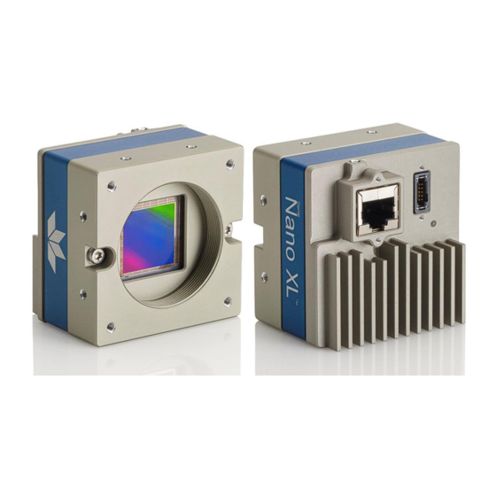
Page 27: Led Indicator
Camera Mounts 10 Pin (4 sides) I/O & Power Status LED Ethernet Supports Connector Thumbscrew (supports PoE) Secured Cables Genie Nano-10G – Rear View LED Indicator The Genie Nano-10G has one multicolor LED to provide a simple visible indication of camera state, as described below. -
Page 28: Led States On Power Up
• Persistent IP (if enabled) • DHCP (if a DHCP server is present such as the Teledyne DALSA Smart DHCP server) • Link-Local Address (always enabled as default) The factory default IP configuration for Nano-10G is Persistent IP disabled and DHCP enabled with LLA always enabled as per the GigE Vision specification. -
Page 29: Preventing Operational Faults Due To Esd
0 volt return line is not necessarily connected to earth ground. Teledyne DALSA has performed ESD testing on Nano-10G cameras using an 8 kilovolt ESD generator without any indication of damage to camera hardware (however the camera might reboot and reconnect to the application). -
Page 30: Using Nano-10G With Sapera Lt
Using Nano-10G with Sapera LT A Genie Nano-10G camera installation with the Teledyne DALSA Sapera LT API generally follows the sequence described below. Network and Computer Overview • Nano-10G needs to connect to a computer with a GigE network adapter, either built-in on the computer motherboard or installed as a third-party PCI adapter. -
Page 31: Installation
Download and install Sapera LT SDK 8.70 (or later), which automatically provides GigE Vision support. • Optional: If the Teledyne DALSA Sapera LT SDK package is not used, install the Genie Nano-10G firmware and user manuals only. Follow the on screen prompts. -
Page 32: Gige Server Status
Jumbo Frames. These should be optimized for use with the Nano-10G during the installation. Refer to the NetworkOptimizationGuide.pdf for optimization information (available with the Sapera LT installation [C:\Program Files\Teledyne DALSA\Network Interface] or on the Start menu under Teledyne DALSA). 24 • Using Nano-10G with Sapera LT... -
Page 33: Quick Test With Camexpert (Windows)
Quick Test with CamExpert (Windows) When the Genie Nano-10G camera is connected to a Gigabit network adapter on a host computer, testing the installation with CamExpert is a straightforward procedure. • Open Sapera CamExpert by double-clicking the desktop icon created during installation. •... -
Page 34: About The Device User Id
About the Device User ID An imaging application can use any one of these attributes to identify a camera: IP address, MAC address, serial number, or Device User ID. The Device User ID feature is used to provide the Nano-10G a custom name for easy identification. This is especially useful when multiple cameras are connected to the network. -
Page 35: Operational Reference
Operational Reference Using CamExpert with Genie Nano-10G Cameras The Sapera CamExpert tool is the interfacing tool for GigE Vision cameras and is supported by the Sapera library and hardware. CamExpert allows a user to test camera settings and functions. Additionally, CamExpert saves the Nano-10G user settings configuration to the camera or saves multiple configurations as individual camera parameter files on the host system (*.ccf). -
Page 36: Camexpert View Parameters Option
• Device Selector pane: Lists all installed GigE Vision or Sapera acquisition devices. • Parameters pane: Allows viewing or changing the acquisition parameters that are supported by the acquisition device. • Display pane: Provides a live or single frame acquisition display. Frame buffer parameters are shown in an information bar above the image window. -
Page 37: Camera Feature Categories
(indicated by DFNC), versus the GenICam Standard Features Naming Convention (SFNC tag is not shown). Features listed in the description table that are tagged as Invisible are usually for Teledyne DALSA or third-party software usage—not typically needed by end user applications. -
Page 38: Camera Information Category
Camera Information Category Camera Information features include camera model, firmware version, etc. GigE Vision applications retrieve this information to identify the camera along with its characteristics. These features are typically read-only. A notable exception is the Device User ID, which can be set by the user. Camera Information Feature Descriptions Display Name Feature &... - Page 39 Display Name Feature & Values Description Device Version & View Command to perform an internal test which will determine 1.00 Device Built-In Self Test deviceBIST the device status. (W) DFNC Beginner Device Built-In Self Test Status deviceBISTStatus Return the status of the device Built-In Self-Test. Possible 1.00 return values are device-specific.
- Page 40 Display Name Feature & Values Description Device Version & View Power-up Configuration Selector UserSetDefault Specify the camera configuration set to load and make 1.00 active on camera power-up or reset. The camera Invisible configuration sets are stored in camera non-volatile memory.
-
Page 41: Power-Up Configuration Dialog
Power-up Configuration Dialog CamExpert provides a dialog box which combines the features to select the camera power-up state and for the user to save or load a Nano-10G camera state. Camera Power-up Configuration The first list allows the user to select the camera configuration state to load on power-up (see UserSetDefaultSelector). -
Page 42: Sensor Control Category
Sensor Control Category The Genie Nano-10G Sensor Control category groups sensor-specific parameters, such as frame rate, exposure time, and gain. Sensor Control Feature Descriptions Display Name Feature & Values Description Device Color Version & View Defines the scan type of the device’s sensor. 1.00 Device Scan Type DeviceScanType... - Page 43 Display Name Feature & Values Description Device Color Version & View Acquisition Frame Rate Control Set the frame control method used in free 1.00 acquisitionFrameRateControlMode Mode running mode. Guru DFNC Note that this feature applies only to sensor acquisitions, not internal test images. Programmable Programmable The camera frame rate is controlled by the...
- Page 44 Display Name Feature & Values Description Device Color Version & View Selects which gain is controlled when adjusting 1.00 Gain Selector GainSelector gain features. Beginner Sensor Analog SensorAnalog Apply an analog gain adjustment within the DFNC sensor to the entire image. Sensor Digital Red SensorDigitalRed Apply a digital gain adjustment within the sensor...
-
Page 45: Gain And Black Level Details
(present at the sensors native bits per pixel) to fall within one 8-bit value, thus the noise becomes hidden. Bayer Mosaic Pattern Genie Nano-10G Color cameras output raw Bayer image data using the mosaic pattern shown below. Teledyne DALSA Sapera CamExpert tool interprets the raw Bayer output when the user enables the Pre-Processing Software Bayer Decoder. -
Page 46: Auto-Brightness Control Category
Auto-Brightness Control Category The Genie Nano-10G Auto-Brightness features are used to configure the automatic gain function. Genie Nano-10G camera models implement different sensors, which may support different features or none from this category. Auto-Brightness Feature Descriptions Display Name Feature & Values Description Device Version &... - Page 47 Display Name Feature & Values Description Device Version & View Auto-Brightness Target Sets the auto-brightness target Range Variation in (DN). An 1.00 autoBrightnessTargetRangeVariation Variation autoBrightnessTarget value within this range is considered Expert valid and will not be compensated. DFNC Auto-Brightness Algorithm autoBrightnessAlgorithm Specifies the auto-brightness algorithm used to calculate the 1.00...
-
Page 48: Using Auto-Brightness
Using Auto-Brightness The Auto-Brightness features are designed to maintain consistent brightness (or image intensity) in situations where lighting varies. These features benefit from being optimized for each application's lighting. The information below describes making these adjustments and the feature interdependencies. All feature example settings and acquisitions examples below are made using the Sapera CamExpert tool. -
Page 49: Auto-Gain
Auto-Gain An alternative method of automating exposure control is by varying the Nano-10G Digital Gain. The user needs to note that the digital gain stage is limited to a small positive multiplier and will have the side effect of increasing digital noise. -
Page 50: I/O Control Category
I/O Control Category The Genie Nano-10G I/O controls, as shown by CamExpert, has features used to configure external inputs and acquisition actions based on those inputs, plus camera output signals to other devices. I/O Control Feature Descriptions Display Name Feature & Values Description Device Version... - Page 51 Display Name Feature & Values Description Device Version & View Specifies the internal signal or physical input line to use as the 1.00 Trigger Source TriggerSource trigger source. The selected trigger must have its TriggerMode set Beginner to ON. See Input Signals Electrical Specifications. Line 1 Line1 Select Line 1 (and associated I/O control block) to use as the...
- Page 52 Display Name Feature & Values Description Device Version & View Specify the current electrical format of the selected physical input 1.00 Line Format LineFormat or output. (RO) Expert Opto-Coupled OptoCoupled The line is opto-coupled. Line Mode LineMode Reports if the physical Line is an Input or Output signal. (RO) 1.00 See Input Signals Electrical Specifications.
- Page 53 Display Name Feature & Values Description Device Version & View Sets the delay before the output line pulse signal. Applicable for 1.00 Output Line Pulse Delay outputLinePulseDelay the OutputLineSource feature. Beginner DFNC Output Line Pulse Duration outputLinePulseDuration Sets the width (duration) of the output line pulse in microseconds. 1.00 Beginner DFNC...
-
Page 54: I/O Module Block Diagram
I/O Module Block Diagram Timer and Counter Module TimerEnd Event Timer Input Event Driven Line Line Input Line Selector = Detection Counter Debouncer inverter Line 1 to 4 Level CounterEnd Event Physical Line Trigger Module Line Mode Input Trigger Signal Trigger LineStatus Trigger... -
Page 55: Input Line Details
• Trigger Source=Timestamp Modulo Event: The Timestamp Modulo event is used as the internal trigger source. • Trigger Source=Action 1 or Action 2: The Action 1 or Action 2 broadcast command is used as the internal trigger source. Input Line Details The general purpose input line signals are connected to I/O lines 1 and 2, which have the following features for control or status indication. -
Page 56: Triggeroverlap=Readout
TriggerOverlap=Readout Trigger is accepted at the beginning of the frame readout. The “End of Exposure to Start of Readout” time is sensor-dependent. Diagram Conditions: • TriggerSelector=FrameStart (i.e., Single Frame Trigger(Start)) • TriggerMode=On • ExposureMode=Timed • ExposureAlignment=Synchronous • TriggerActivation=RisingEdge • TriggerOverlap=Readout •... -
Page 57: Triggeroverlap=Readout With Short Exposure
TriggerOverlap=Readout with Short Exposure This special condition describes the case of a short exposure relative to the readout period. A trigger received before the end of the frame readout is latched and delayed until such time that the following short exposure will end with the end of the previous frame readout. -
Page 58: Triggeroverlap=Readout And Exposuremode=Triggerwidth
TriggerOverlap=Readout and ExposureMode=TriggerWidth This special condition describes the case of a short TriggerWidth exposure relative to the readout period. If the next Trigger input signal occurs during the previous frame readout, attempting to stop the frame active period before the current readout is completed, the camera will continue the second exposure until the previous readout is completed. -
Page 59: Triggeroverlap=Off And Exposuremode=Triggerwidth
TriggerOverlap=Off and ExposureMode=TriggerWidth Diagram Conditions: • TriggerSelector=FrameStart (i.e., Single Frame Trigger(Start)) • TriggerMode=On • ExposureMode=TriggerWidth • ExposureAlignment=Synchronous • TriggerActivation=RisingEdge • TriggerOverlap=Off • TriggerDelay=0 TriggerOverlap= Off and ExposureMode=TriggerWidth Exclusion Region Exclusion Region Trigger Input Exposure 2 Exposure 1 Frame Exposure Readout 1 Readout 2 Frame Readout Frame 1 Active period... - Page 60 Camera Output LOAD Examples of Logic HI and Logic LO output circuits 52 • Operational Reference Nano-10G Series GigE Vision Cameras...
-
Page 61: Counter And Timer Control Category
Counter and Timer Control Category The Genie Nano-10G counter and timer controls, as shown by CamExpert, has parameters used to configure acquisition counters and timers for various input lines and signal edge detection. Counter and Timer Control Feature Descriptions Display Name Feature &... - Page 62 Display Name Feature & Values Description Device Version & View Counter Start Source Select the counter start source. Counter increments from 0 to the 1.00 counterStartSource value of the counterDuration feature. Expert DFNC Counter is stopped. Acquisition Start AcquisitionStart Counter starts on the reception of the Acquisition Start event. Acquisition End AcquisitionEnd Counter starts on the reception of the Acquisition End event.
- Page 63 Display Name Feature & Values Description Device Version & View Selects the signal source to reset the counter. After a reset the 1.00 Counter Reset Source counterResetSource counter waits for the next countStartSource signal or event. Expert DFNC Reset Cmd Reset on reception of the Reset Icommand.
- Page 64 Display Name Feature & Values Description Device Version & View Select the trigger source to start the timer. 1.00 timerStartSource Timer Start Source The Event Control section provides details and timing diagrams for Expert the supported events. DFNC TimerReset Cmd Starts with the reception of the TimerReset Icommand.
-
Page 65: Counter And Timer Group Block Diagram
Counter and Timer Group Block Diagram Timer and Counter Module TimerEnd Event Timer Input Event Driven Line Line Input Line Selector = Detection Counter Debouncer inverter Line 1 to 4 Level CounterEnd Event Physical Line Trigger Module Line Mode Input Trigger Signal Trigger LineStatus... -
Page 66: Example: Counter Start Source = Counterend (Itself)
Example: Counter Start Source = CounterEnd (itself) CounterStartSource=CounterEnd (itself) Countermode=Active Countermode=OFF CounterEnd Event Generated Counter is CounterWait Counter is Counter IDLE Trigger Active Completed Counter is incrementing CounterStartSource= CounterEnd (itself) Counter Reset CMD CounterResetSource=CounterEnd • Counter starts when Counter Mode is set to Active. •... -
Page 67: Example: Counterstartsource = Line (Edge Base) Example
Example: CounterStartSource = Line (Edge Base) Example CounterStartSource= Line (Edge Base ) Example 2 Countermode=Active Countermode=OFF CounterEnd Event Generated CounterResetSource =CounterEnd(Itself) Counter STATUS Counter is CounterWait Counter Active Active Active Active IDLE Start Completed Counter Register CounterDuration=12 CounterStartSource= Line 1 CounterTriggerActivation= Falling Edge any Tick in... -
Page 68: Advanced Processing Control Category
Advanced Processing Control Category The Genie Nano-10G Advanced Processing controls, as shown by CamExpert, groups parameters used to configure LUT mode controls on monochrome cameras. Genie Nano-10G cameras are available in a number of models implementing different sensors and image resolutions which may not support the full feature set defined in this category. - Page 69 Display Name Feature & Values Description Device Version & View 1.00 LUT Current Active Set lutCurrentActiveSet Specifies the current LUT to use. Expert User Defined 1 UserDefined1 Sets the current LUT as User Defined 1. DFNC User Defined 2 UserDefined2 Sets the current LUT as User Defined 2.
-
Page 70: Lookup Table (Lut) Overview
Lookup Table (LUT) Overview The Genie Nano-10G cameras include a user programmable LUT table as a component of its embedded processing features. A LUT is used for operations such as gamma adjustments, invert and threshold processes. The camera LUT table are dependent on the sensor (per pixel – see feature LUT Size) and is illustrated in the following figure (see Processing path bits per pixel). -
Page 71: Gamma Correction Factor
Gamma Correction Factor The following graphic shows LUT output data as a function of the gamma correction factor programmed by the user. An 8-bit LUT is shown as an example and importantly the graphic is not to scale. • As Gamma Correction is reduced in value to the minimum allowed, the nonlinear output of acquisition data through the LUT effectively boosts low value data. -
Page 72: Defective Pixel Replacement
Nano-10G model. The following XML code sample forms the template for the user to build bad pixel maps for any of their Nano-10G cameras. Note: Identifying bad pixels is left to the user’s discretion, but Teledyne DALSA technical support can provide guidance. -
Page 73: Color Defective Pixel Replacement Algorithm Description
• Replace defective pixel (row n, pix5) with the right diagonal pixel on the previous line (row n-1, pix6) if the left diagonal pixel is also defective. • Replace defective pixel (row n, pix1) with the corresponding pixel on the previous line (row n-1, pix1) if both left and right diagonal pixels on the previous line are defective. -
Page 74: Color Processing Category
Color Processing Category The Nano-10G Color Processing category, as shown by CamExpert, has parameters used to configure the color camera white balance/color balance features. Color Processing Control Feature Descriptions Display Name Feature & Values Description Device Version & View Automatic White Balance BalanceWhiteAuto Controls the mode for automatic white balancing between the color 1.00... -
Page 75: Color Processing Functional Overview
Color Processing Functional Overview Nano-10G color cameras provide White Balance controls (automatic or manual). These features are described below in more detail. Note that computer monitors have wide variations in displaying color. Users should consider using professional monitors which have factory calibrated fixed presets conforming to sRGB or AdobeRGB color spaces. -
Page 76: Lens Shading Correction Category
Lens Shading Correction Category The Nano-10G Lens Shading Correction controls, as shown by CamExpert, has parameters used to configure the lens shading correction features. Lens Shading Correction Feature Descriptions Display Name Feature & Values Description Device Version & View Lens Shading Correction Mode lensShadingCorrectionMode Sets the mode for the lens shading correction. - Page 77 Display Name Feature & Values Description Device Version & View DFNC Lens Shading Algorithm Buffer Height lensShadingCorrectionAlgorithmBufferHeight Invisible Lens Shading Algorithm Gain Max lensShadingCorrectionAlgorithmGainMax DFNC Invisible Lens Shading Algorithm Gain Min lensShadingCorrectionAlgorithmGainMin DFNC Invisible Lens Shading Algorithm Gain Divisor lensShadingCorrectionAlgorithmGainDivisor DFNC Invisible Lens Shading Algorithm Gain Base...
-
Page 78: Lens Shading Calibration
Lens Shading Calibration It is recommended that a Lens Shading Calibration procedure be done for any Nano-10G/Lens combination. Calibration eliminates any lens vignetting in the image corners or any other shading differences across the image field. Calibration will allow using a lens with a slightly smaller image circle that does not quite evenly expose the whole sensor. -
Page 79: Cycling Preset Mode Control Category
Cycling Preset Mode Control Category The Genie Nano-10G Cycling Preset controls, as shown by CamExpert, has parameters used to configure the camera Cycling features. Cycling controls allow the user to configure a number of camera operational states and then have the camera automatically switch between states in real-time. Only the features programmed to change are updated when switching between camera states, thus ensuring immediate camera response. - Page 80 Display Name Feature & Values Description Device Color Version & View Select the activation mode for the selected Input Line 1.00 Trigger Input Line Activation cyclingPresetIncrementalActivation source. This is applicable only for external line inputs. Expert DFNC Rising Edge RisingEdge The source is considered valid on the rising edge of the line source signal (after being processed by the line inverter feature).
- Page 81 Display Name Feature & Values Description Device Color Version & View Selects the feature to control by the 1.00 Features Activation Selector cP_FeaturesActivationSelector cP_FeaturesActivationMode feature. Expert DFNC Exposure Time ExposureTime The cP_FeaturesActivationMode feature controls the exposure time. Exposure Delay ExposureDelay The cP_FeaturesActivationMode feature controls the exposure delay.
- Page 82 Display Name Feature & Values Description Device Color Version & View Selects which color gain is controlled with the 1.00 Cycling White Balance Selector cP_BalanceRatioSelector cp_BalanceRatio feature. Expert DFNC Note: cycling white balance gains is only available when Automatic White Balance and Auto-Brightness Mode are disabled.
-
Page 83: Using Cycling Presets-A Simple Example
Using Cycling Presets—a Simple Example As presented in this category’s overview, the cycling preset features allows setting up camera configurations that can change dynamically and repeatedly, with minimum overhead. The features that change along with the trigger for the feature change are preprogrammed in the camera. Additionally, a set of preset features can be updated while the camera is acquiring with a different preset. -
Page 84: Cycling Reset Timing Details
Cycling Reset Timing Details This section describes the Nano-10G Cycling function with two cycling feature configurations. These configurations (or cases) are dependent on the cycling preset increment source as follows: • Internal Synchronous Increment: Where the preset increment source is either Start of Frame or Valid Frame Trigger (cyclingPresetIncrementalSource= StartOfFrame or ValidFrameTrigger). -
Page 85: Case 2: Cycling With External Asynchronous Increment
Case 2: Cycling with External Asynchronous Increment With an External Asynchronous Cycling Increment, a cycling reset command executes immediately and sets the cycling preset to set number 1. Increment Source Increment Source cyclingPresetIncrementalSource Increment Source cyclingPresetIncrementalSource cyclingPresetIncrementalSource Frame Acquisition 1 Frame Acquisition 3 Frame Acquisition 4 Frame Acquisition 2... -
Page 86: Image Format Control Category
Image Format Control Category The Genie Nano-10G Image Format parameters are used to configure camera output pixel format, image cropping, binning, and multiple ROI settings, or to select a test output image when tested without a lens. Image Format Control Feature Descriptions Display Name Feature &... - Page 87 Display Name Feature & Values Description Device Color Version & View Format of the pixel provided by the device. Contains all format 1.00 Pixel Format PixelFormat information as provided by PixelCoding, PixelSize, Beginner PixelColorFilter, combined in one single value. Monochrome 8-Bit Mono8 Monochrome 8-bit.
- Page 88 Display Name Feature & Values Description Device Color Version & View 1.00 Width Width Width of the Image provided by the device (in pixels). Beginner Height Height Height of the Image provided by the device (in lines). 1.00 Beginner Multiple ROI Mode multipleROIMode Enable the Multiple ROI (Region of Interest) per image feature.
- Page 89 Display Name Feature & Values Description Device Color Version & View Horizontal offset (in pixels) from the origin to the selected ROI 1.00 ROI Offset X multipleROIOffsetX (Region of Interest). Expert DFNC ROI Offset Y multipleROIOffsetY Vertical offset (in pixels) from the origin to the selected ROI 1.00 (Region of Interest).
- Page 90 Display Name Feature & Values Description Device Color Version & View 1.00 Pixel Color Filter PixelColorFilter Indicates the type of color filter applied to the image. < RO > Invisible None None No filter applied on the sensor. Bayer GR BayerGR For BayerGR, the 2x2 mosaic alignment is GR/BG.
-
Page 91: Width And Height Features For Partial Scan Control
Width and Height Features for Partial Scan Control Width and Height controls along with their respective offsets, allow the Genie Nano-10G to grab a region of interest (ROI) within the full image frame. Besides eliminating post acquisition image cropping done by software in the host computer, a windowed ROI grab reduces the bandwidth required on the Gigabit Ethernet link since less pixels are transmitted. -
Page 92: Maximum Frame Rate Examples
Maximum Frame Rate Examples The following tables provide the maximum frame rates for different partial scan sizes using free-running mode (internal trigger) with the minimum exposure time (Standard Design Firmware). Vertical Lines Acquired M/C6200 M/C8200 5420 4504 3008 2176 2056 1536 1024 1170... -
Page 93: Using The Multiple Roi Mode
Horizontal Crop Horizontal Offset Width Using the Multiple ROI Mode Genie Nano-10G monochrome cameras implement the Multiple ROI mode (region of interest) features, which allow having 2 to 16 smaller image ROI areas versus the single ROI area possible with vertical and horizontal crop functions. -
Page 94: Example: Two Horizontal Roi Areas (2X1)
Example: Two Horizontal ROI Areas (2x1) ROI (x1,y1) ROI (x2,y1) ROI (x1,y1) ROI (x2,y1) Camera Outputs only the 2 ROI Areas 2 ROI Areas Defined • Note that ROI(x1, y1) defines the height of any ROI in that row. • ROI(x2, y1) can have a different width. -
Page 95: Example: Actual Sample With Six Roi Areas (3X2)
Example: Actual Sample with Six ROI Areas (3x2) This example uses the example problem of solder inspection of certain components on a PCB. The image below of a sample PCB shows 6 ROI areas highlighted by the yellow overlay graphics (manually added to this example). Note how the top row ROI areas may be larger than ideal due to height and width requirements of ROI areas in the second row;... -
Page 96: Binning Function And Limitations
Binning Function and Limitations Binning is the process where the charge on two (or more) adjacent pixels is combined. This results in increased light sensitivity since there is twice the sensor area to capture photons. The sensor spatial resolution is reduced but the improved low-light sensitivity plus lower signal-noise ratio may solve a difficult imaging situation. -
Page 97: Internal Test Pattern Generator
Internal Test Pattern Generator The Genie Nano-10G camera includes internal test patterns which easily confirm camera installations, without the need for a camera lens or proper lighting. Use CamExpert to easily enable and select the any of the Nano-10G test patterns. Select live grab to see the pattern output. -
Page 98: Metadata Control Category
The Genie Nano-10G Metadata Controls category is used to enable and select inclusion of chunk data with the image payload (as specified by the specification GigE Vision 1.2). Teledyne DALSA provides header files for developers managing Genie Nano-10G LUT data and chunk payload data as supported by GigE Vision 1.2. Refer to Extracting Metadata Stored in a Sapera Buffer. - Page 99 Display Name Feature & Values Description Device Version & View Metadata Selector 1.00 ChunkSelector Selects the specific metadata to control, when enabled. Expert OffsetX OffsetX Add the OffsetX value used during the image acquisition to the metadata attached to the image. OffsetY OffsetY Add the OffsetY value used during the image acquisition to the metadata...
-
Page 100: Extracting Metadata Stored In A Sapera Buffer
Extracting Metadata Stored in a Sapera Buffer The Sapera CamExpert tool provides a tab (when the Metadata feature is enabled) to view the metadata of the last frame capture, as shown by the following image. Sapera LT provides two methods to view metadata (SapMetadata class). Alternatively, the Sapera LT installation includes a demo program called GigEMetaDataDemo.exe, which will grab a number of frames and display the metadata or save it to a file (.csv). - Page 101 When an internal Nano-10G Test Image is selected, the Metadata feature values for Exposure Time (ExposureTime) and Exposure Delay (exposureDelay) are not valid values and must be ignored. When in free running (not triggered) mode, the Metadata value for feature Exposure Delay (exposureDelay) is not a valid value and must be ignored.
-
Page 102: Acquisition And Transfer Control Category
Acquisition and Transfer Control Category The Genie Nano-10G Acquisition and Transfer controls category in CamExpert has parameters used to configure the optional acquisition modes of the device. Acquisition and Transfer Control Feature Descriptions Display Name Feature & Values Description Device Version &... - Page 103 Display Name Feature & Values Description Device Version & View Arms the device before an AcquisitionStart command. This optional 1.00 Acquisition Arm Cmd AcquisitionArm command validates all the current features for consistency and Guru prepares the device for a fast start of the acquisition. If not used explicitly, this command is automatically executed at the first AcquisitionStart but will not be repeated for subsequent ones unless a data transfer related feature is changed in the device.
- Page 104 Display Name Feature & Values Description Device Version & View Device Registers Announces end of registers streaming and performs validation for 1.00 DeviceRegistersStreamingEnd Streaming End registers consistency before activating them. Invisible Device Feature Streaming DeviceFeaturePersistenceStart Announces the start of feature streaming without immediate checking 1.00 Start for consistency.
-
Page 105: Acquisition Buffering
Acquisition Buffering All acquisitions are internally buffered and transferred as fast as possible to the host system. This internal buffer allows uninterrupted acquisitions no matter of any transfer delays that might occur (such as acquisition frame rates faster that the Gigabit Ethernet link or the IEEE Pause frame). Only when the internal buffer is consumed would an Image Lost Event be generated. -
Page 106: Action Control Category
Action Control Category The Genie Nano-10G Action Control group includes features related to the control of the Action Command mechanism for the device. Action Control Feature Descriptions Display Name Feature & Values Description Device Version & View 1.00 Action Selector ActionSelector Selects the action command to configure. - Page 107 Display Name Feature & Values Description Device Version & View Select the camera event that will generate an action command on the 1.00 Action Command Source actionCMDSource network. Guru DFNC Action command is disabled. ValidFrameTrigger ValidFrameTrigger A valid frame trigger event will generate an action command. InvalidFrameTrigger InvalidFrameTrigger An invalid frame trigger event will generate an action command.
-
Page 108: Gige Vision Action Command Reference
Cameras receiving the Action Command broadcast may have one or multiple functions acting on that received command. Please refer to the GigE Vision® Specification — version 2.0 RC6, for configuration and usage details. Contact Teledyne DALSA Support and request example code for Action Command usage. Nano-10G Features Supporting Action Command Feature Category... -
Page 109: Event Control Category
Event Control Category The Genie Nano-10G Event control, as shown by CamExpert, has parameters used to configure Camera Event related features. Event Control Feature Descriptions Display Name Feature & Values Description Device Version & View Timestamp Latch Cmd timestampControlLatch Latch the current timestamp internal counter value in the 1.00 timestampValue feature. - Page 110 Display Name Feature & Values Description Device Version & View Specifies the internal event or signal that will latch the timestamp 1.00 Timestamp Latch Source timestampLatchSource counter into the timestamp buffer. Expert DFNC Frame Start FrameStart The timestamp is latched on frame start. Timestamp Reset Cmd timestampControlReset Resets the timestamp counter to 0.
- Page 111 Display Name Feature & Values Description Device Version & View 1.00 Event Statistic Selector eventStatisticSelector Selects which Event statistic to display. Expert Invalid Frame Trigger InvalidFrameTrigger Counts the frame triggers occurring in an invalid Trigger region. DFNC Image is acquired but lost before it’s been transferred. Image Lost ImageLost Packet Resend...
- Page 112 Display Name Feature & Values Description Device Version & View PTP Status Specifies dynamically the current PTP state of the device. (ref: 1.00 ptpStatus IEEE Std 1588-2008) Expert DFNC Initializing Initializing The port initializes its data sets, hardware, and communication facilities.
- Page 113 Display Name Feature & Values Description Device Version & View PTP Servo Status 1.00 ptpServoStatus Specifies the IEEE1588 servo status. Expert Unlocked Unlocked The servo is not yet ready to track the master clock. DFNC Synchronizing Synchronizing The servo is unlocked and synchronizing to the master clock. Locked Locked The servo is adjusting (syntonizing) to the master clock.
- Page 114 Display Name Feature & Values Description Device Version & View Timestamp Modulo Actual Displays the actual modulo event start time as used by the 1.00 timestampModuloActualStartTime device. When the user specified “timestampModuloStartTime” is Start Time Expert in the future, timestampModuloActualStartTime= DFNC timestampModuloStartTime.
-
Page 115: Basic Exposure Events Overview
Basic Exposure Events Overview The following timing graphic shows the primary events related to a simple acquisition. TimeStamp Latch FrameStart Event FrameActive Frame Inactive Frame Inactive Exposure Exposure Delay ReadOut ExposureStart Event ExposureEnd Event Events Associated with Triggered Synchronous Exposures The following timing graphic shows the primary events and acquisition timing associated with a synchronous exposure of two individually triggered frames. -
Page 116: Events Associated With Triggered Multiple Frame Synchronous Exposures
Events Associated with Triggered Multiple Frame Synchronous Exposures The following timing graphic shows the primary events and acquisition timing associated with a synchronous exposure of two frames from a single trigger event. Multiple FrameActive (exposureAlignment=Synchronous ) Input Signal ValidFrameTrigger Event Event TriggerDelay Invalid Frame Trigger Period... -
Page 117: Ptp Master Clock Identity
PTP Master Clock Identity The clock ID of the current best master is an Extended Unique Identifier (EUI)-64 “64-bit ID”, converted from the 48-bit MAC address, by inserting 0xfffe at the middle of the MAC address. • The standard MAC address in human-friendly form is six groups of two hexadecimal digits as this example shows (excluding spaces): “0a 1b 2c 3d 4e 5f”... -
Page 118: Case 1: Simple Repeating Acquisitions As Upcoming Events
Case 1: Simple Repeating Acquisitions as Upcoming Events Conditions: • initial timestampControlReset resets Timestamp counter • timestampModuloStartTime at 20 • timestampModulo = 10 • timestampModuloActualStartTime = First Event generated (F1) After the Timestamp Reset, the first acquisition is made when the Modulo reaches the +10 tick Timestamp count, following the programmed start time. -
Page 119: Case 2: Potential Uncertainness To The Start Time
Case 2: Potential Uncertainness to the Start Time Conditions: • initial timestampControlReset resets Timestamp counter • timestampModuloStartTime at < 20 • timestampModulo = 10 • timestampModuloActualStartTime = first event (F1) Case 2 differs only from case 1 by showing that there is a period of uncertainty if the start time is too close to the first modulo count that follows. -
Page 120: Case 3: Timer Reset Before The Actual Start Time
Case 3: Timer Reset Before the Actual Start Time Conditions: • initial timestampControlReset resets Timestamp counter • timestampModuloStartTime at 20 • timestampModulo = 10 • second timestampControlReset at count 25 • timestampModuloActualStartTime = first event (F1) After the initial Timestamp Reset which starts the Timestamp counter, the Modulo start time is at 20. The Modulo 10 actual start time for the first acquisition is at Timestamp 30 (as described in Case 1). -
Page 121: Case 4: Timer Reset After The Actual Start Time
Case 4: Timer Reset After the Actual Start Time Conditions: • initial timestampControlReset resets Timestamp counter • timestampModuloStartTime at 20 • timestampModulo = 10 • timestampModuloActualStartTime = first event (F1) • second timestampControlReset at 35 This case describes the Modulo process if there is a Timestamp counter reset after a modulo controlled acquisition occurs. -
Page 122: Case 5: Changing Timestampmodulo During Acquisitions
Case 5: Changing timestampModulo During Acquisitions Conditions: • initial timestampControlReset resets Timestamp counter • timestampModuloStartTime at 20 • timestampModulo = 10 • timestampModuloActualStartTime = first event (F1) • timestampModulo changes to 20 Case 5 shows that the Modulo value can be changed dynamically. Using the simple example of case 1, after the second acquisition (F2) the Modulo value is changed from 10 to 20. -
Page 123: Gige Vision Transport Layer Control Category
GigE Vision Transport Layer Control Category The Genie Nano-10G GigE Vision Transport Layer control, as shown by CamExpert, has parameters used to configure features related to GigE Vision specification and the Ethernet Connection. GigE Vision Transport Layer Feature Descriptions Display Name Feature &... - Page 124 Display Name Feature & Values Description Device Version & View Maximum speed the device will advertise during 1.00 Maximum Link Speed gevLinkSpeedLimit autonegotiation. Changes will take effect on the next boot. DFNC Guru 5 GigE Speed_5000 The link is limited up to the 5000Base-t (5 GigE) link speed.
- Page 125 Display Name Feature & Values Description Device Version & View Disables the GVCP (GigE Vision Control Protocol) 1.00 GVCP Heartbeat Disable GevGVCPHeartbeatDisable heartbeat monitor. This allows control switchover to an Expert application on another device. Communication Timeout (in ms) GevMCTT Provides the transmission timeout value in milliseconds.
- Page 126 Display Name Feature & Values Description Device Version & View Gev Supported Option Selector Selects the GEV option to interrogate for existing support. 1.00 GevSupportedOptionSelector (RO) Invisible IPConfigurationLLA IPConfigurationDHCP IPConfigurationPersistentIP StreamChannelSourceSocket MessageChannelSourceSocket CommandsConcatenation WriteMem PacketResend Event EventData PendingAck Action PrimaryApplicationSwitchover ExtendedStatusCodes DiscoveryAckDelay DiscoveryAckDelayWritable...
-
Page 127: Defaults For Devicepacketresendbuffersize
Display Name Feature & Values Description Device Version & View Indicates the port to which the device must send 1.00 Gev MCP HostPort GevMCPHostPort messages. (RO) Invisible Gev MCDA GevMCDA Indicates the destination IP address for the message 1.00 channel. (RO) Invisible Gev MCSP GevMCSP... -
Page 128: File Access Control Category
File Access Control Category The File Access control in CamExpert allows the user to quickly upload various data files to the connected Genie Nano-10G. The supported data files are for firmware updates, and dependent on the Nano-10G model, LUT tables, Defective Pixel Maps, and other Sapera file types. File Access Control Feature Descriptions The File Access Control is implemented as a dialog. - Page 129 Display Name Feature & Values Description Device Version & View Executes the operation selected by File Operation Selector on the 1.00 File Operation Execute FileOperationExecute selected file. Guru File Open Mode FileOpenMode Selects the access mode used to open a file on the device. 1.00 Guru Read...
-
Page 130: Updating Firmware Via File Access In Camexpert
Updating Firmware via File Access in CamExpert The CamExpert File Access tool allows quick firmware changes or updates, when available for your Genie Nano- 10G model. 1. In the File Access Control category, click Setting next to Upload/Download File. The File Access Control dialog opens. -
Page 131: Open Source Software Licenses
Open Source Software Licenses The Sapera CamExpert file access tool allows downloading the Open Source Software Licenses statement directly from the installed Nano-10G firmware. 1. In the File Access Control category, click Setting next to Upload/Download File. The File Access Control dialog opens. -
Page 132: Gige Vision Host Control Category
GigE Vision Host Control Category The GigE Vision Host controls as shown by CamExpert, has parameters used to configure the host computer system GigE Vision features used for Genie Nano-10G networking management. None of these parameters are stored in any Genie Nano-10G camera. These features allow optimizing the network configuration for maximum Nano-10G bandwidth. -
Page 133: Implementing Trigger-To-Image Reliability
In a complex imaging system, a lot can go wrong at all points – from initial acquisition to camera processing, to data transmission. Teledyne DALSA provides features, events, and I/O signals that provide the system designer with the tools to qualify the system in real time. -
Page 134: Nano-10G Features For T2Ir Monitoring
Nano-10G Features for T2IR Monitoring The following table presents some of the Nano-10G camera features developers can use for T2IR monitoring. The output line signals would interface to other external devices. Camera Status Monitoring Device Built-In Self Test deviceBIST Device Built-In Self Test Status deviceBISTStatus Device Temperature Selector DeviceTemperatureSelector... -
Page 135: Technical Specifications
Technical Specifications Both 2D and 3D design drawings are available for download from the Teledyne DALSA web site [https://www.teledynedalsa.com/en/products/imaging/cameras/genie-nano-10gige/]. Mechanical Specifications — M42 Mount Technical Specifications • 127 Nano-10G Series GigE Vision Cameras... -
Page 136: Additional Notes On Genie Nano-10G Identification And Mechanical
Additional Notes on Genie Nano-10G Identification and Mechanical Identification Label Genie Nano-10G cameras have an identification label applied to the bottom side, with the following information: Model Part Number Serial number MAC ID 2D Barcode CE and FCC logo Additional Mechanical Notes Nano-10G supports a screw lock Ethernet cable as described in Ruggedized RJ45 Ethernet Cables. -
Page 137: Sensor Alignment Specification
Sensor Alignment Specification The following figure specifies sensor alignment for Genie Nano-10G where all specifications define the absolute maximum tolerance allowed for production cameras. Dimensions X, Y, Z are in microns and referenced to the Genie Nano-10G mechanical body or the optical focal plane (for the Z-axis dimension). Theta specifies the sensor rotation relative to the sensor’s center and Nano-10G mechanical. -
Page 138: Connectors
Connectors • A single RJ45 Ethernet connector for control and video data to the host Gigabit NIC. Additionally for PoE, the Genie Nano-10G requires an appropriate PoE Class 0 or Class 3 power source device (such as a powered computer NIC, or a powered Ethernet switch, or an Ethernet power injector). For industrial environments, Nano-10G supports the use of screw lock Ethernet cables (see Ruggedized RJ45 Ethernet Cables). -
Page 139: 10-Pin I/O Connector Pinout Details
10-pin I/O Connector Pinout Details Teledyne DALSA makes available optional I/O cables as described in Optional Cable Accessories. Contact Sales for availability and pricing. Pin Number Genie Nano-10G Direction Definition — Camera Power – Ground PWR-GND — Camera Power – DC +10 to +36 Volts PWR-VCC —... -
Page 140: I/O Mating Connector Specifications & Sources
I/O Mating Connector Specifications & Sources For users wishing to build their own custom I/O cabling, use the following product information to expedite your cable solutions. Samtec web information for the discrete connector and a cable assembly with retention clips follows the table. -
Page 141: Power Over Ethernet (Poe) Support
Samtec connector-cable assembly SFSD-05-28-H-03.00-SR w/retention clips “.050” Tiger Eye™ Double Row Discrete Wire Cable Assembly, Socket” Power over Ethernet (PoE) Support Connect power via the I/O or PoE, not both. Although Nano-10G has protection, differences in ground levels may cause operational issues or electrical faults, resulting in camera faults or failure. •... -
Page 142: Input Signals Electrical Specifications
Input Signals Electrical Specifications External Inputs Block Diagram External Input Details • Opto-coupled with internal current limit. • Single input trigger threshold level (TTL standard: < 0.8 V = Logical LOW, > 2.4 V = Logical HIGH. See lineDetectionLevel feature). •... -
Page 143: External Input Ac Timing Characteristics
External Input AC Timing Characteristics Conditions Description Unit Input Pulse 0V – 3V Input Pulse width High µs Input Pulse width Low 1.22 µs Max Frequency Input Pulse 0V – 5V Input Pulse width High µs Input Pulse width Low 1.28 µs Max Frequency... -
Page 144: External Inputs: Using Common Collector Npn Drivers
External Inputs: Using Common Collector NPN Drivers External Input maximum current is limited by the Nano-10G circuits to a maximum of 12 mA. User IO Power (3V-28V) Camera IO Interface External Signal 2 External Signal 1 Imax = 10mA ( Input 2 ) Imax = 10mA ( Input 1 ) ( Common Ground ) -
Page 145: Output Signals Electrical Specifications
Camera IO Interface RS-422 Compatible Transmitter ( Input 2 ) ( Input 1 ) External Signal ( Common Ground ) Only one Input can be used in this configuration. Output Signals Electrical Specifications External Outputs Block Diagram Output Common Power (pin 4) Current Output 2 (pin 8) -
Page 146: External Output Ac Timing Characteristics
External Output AC Timing Characteristics The graphic below defines the test conditions used to measure the Nano-10G external output AC characteristics, as detailed in the table that follows. Output Control Signal Output Common Power Control Signal 100% Camera Output Output Load rise fall... - Page 147 µs) Output d1 (us d2 ( µs) µs) Output load rise ( fall ( out ( Common Current Leading Trailing Power Test (ohm) Rise Time Fall Time Delay Delay 8 mA 1.69 1.2144 0.897 0.811 4.53 16 mA 1.883 1.6192 0.502 0.659 4.45...
-
Page 148: External Outputs: Using External Ttl/Lvttl Drivers
External Outputs: Using External TTL/LVTTL Drivers Camera IO User IO Interface Power ( Output 2 ) Signal 2 ( Output 1 ) Signal 1 ( User IO Power ) (Pull-Down) (Pull-Down) LVTTL/TTL Buffer User IO Ground External Outputs: Using External LED Indicators •... - Page 149 • Alternatively, one external LED can be connected in the Common Anode configuration. User IO Power Camera IO Interface Set resistor (R) value to not ( Output 2 ) exceed output current of = 30mA. ( Output 1 ) Only one Output (1 or 2) can be used in this configuration.
-
Page 150: Using Nano-10G Outputs To Drive Other Nano-10G Inputs
Using Nano-10G Outputs to Drive Other Nano-10G Inputs • A synchronization method where one Nano-10G camera signals other Nano-10G cameras. • Note: One Nano-10G output can drive a maximum of three Nano-10G inputs, as illustrated below. Camera IO User IO Interface Power Do not exceed more then three... -
Page 151: Computer Requirements For Nano-10G Cameras
Hardware Considerations section. Important: 10/100 Mb Ethernet is not supported by the Genie Nano-10G series of cameras. The Genie Nano- 10G Status LED will show that it acquired an IP address (solid Blue), but the camera will not respond or function at these slower connections. -
Page 152: Declarations Of Conformity
Declarations of Conformity Copies of the Declarations of Conformity documents are available on the product page on the Teledyne DALSA website or by request. FCC Statement of Conformance for Class A This equipment complies with Part 15 of the FCC rules. Operation is subject to the following conditions: 1. -
Page 153: Additional Reference Information
Additional Reference Information Choosing a Lens with the Correct Image Circle Each Nano-10G model requires a lens with an image circle specification to fully illuminate the sensor. The following section graphically shows the minimum lens image circle for each Nano-10G model family along with alternative lens types. -
Page 154: Additional Lens Parameters (Application Specific)
The Teledyne DALSA Web site provides information on this potentially complicated issue (Learn > Knowledge Center or Application Notes). -
Page 155: Light Sources
Light Sources Keep these guidelines in mind when selecting and setting up light source: • LED light sources are relatively inexpensive, provide a uniform field, and longer life span compared to other light sources. However, they also require a camera with excellent sensitivity. •... -
Page 156: Back Focal Variance When Using Any Filter
Back Focal Variance when using any Filter Inserting a filter between a lens and sensor changes the back focal point of the lens used. A variable focus lens simply needs to be adjusted, but in the case of a fixed focus lens, the changed focal point needs correction. The following simplified illustration describes this but omits any discussion of the Optics, Physics, and the math behind the refraction of light through glass filter media. -
Page 157: Lens Modeling
Lens Modeling Any lens surrounded by air can be modeled for camera purposes using three primary points: the first and second principal points and the second focal point. The primary points for a lens should be available from the lens data sheet or from the lens manufacturer. -
Page 158: Sensor Handling Instructions
Sensor Handling Instructions This section reviews proper procedures for handling, cleaning, or storing the Genie Nano-10G camera. Specifically, the Genie Nano-10G sensor needs to be kept clean and away from static discharge to maintain design performance. Electrostatic Discharge and the Sensor Cameras sensors containing integrated electronics are susceptible to damage from electrostatic discharge (ESD). -
Page 159: Cleaning The Sensor Window
Ruggedized Cable Accessories Teledyne DALSA provides optional I/O cable assemblies for Genie Nano-10G. Users wishing to build their I/O cabling by starting from available cable packages should consider these popular assemblies described below. Contact Sales for pricing and delivery. -
Page 160: Cable Assembly G5-Aioc-Blunt2M
Cable Assembly G5-AIOC-BLUNT2M 152 • Additional Reference Information Nano-10G Series GigE Vision Cameras... - Page 161 Additional Reference Information • 153 Nano-10G Series GigE Vision Cameras...
-
Page 162: Cable Assembly G3-Aioc-Brkout2M
Cable Assembly G3-AIOC-BRKOUT2M 154 • Additional Reference Information Nano-10G Series GigE Vision Cameras... - Page 163 Additional Reference Information • 155 Nano-10G Series GigE Vision Cameras...
-
Page 164: Nano-10G Generic Power Supply With No I/O
Nano-10G Generic Power Supply with no I/O 156 • Additional Reference Information Nano-10G Series GigE Vision Cameras... -
Page 165: Components Express Right-Angle Cable Assemblies
Components Express Right-Angle Cable Assemblies These cable assemblies can be acquired directly from our partner Components Express. In such cases use the manufacturer’s part number shown on the cable assembly engineering drawing. Cable Assembly: Right-Angle I/O Bunt End Additional Reference Information • 157 Nano-10G Series GigE Vision Cameras... -
Page 166: Cable Assembly: Right-Angle I/O To Euro Block
Cable Assembly: Right-Angle I/O to Euro Block 158 • Additional Reference Information Nano-10G Series GigE Vision Cameras... -
Page 167: Ruggedized Rj45 Ethernet Cables
Ruggedized RJ45 Ethernet Cables Components Express Inc. has available industrial RJ45 CAT6 cables that on one end have a molded shroud assembly with top/bottom thumbscrews, while the other end is a standard RJ45 (one example shown below). These cables are recommended when Nano-10G is installed in a high vibration environment. All Nano-10G versions support this secure Ethernet cable. -
Page 168: Cable Assembly: Right-Angle Ethernet
Cable Assembly: Right-Angle Ethernet 160 • Additional Reference Information Nano-10G Series GigE Vision Cameras... -
Page 169: Right-Angle Cable-Set (Mounted)
Right-Angle Cable-Set (Mounted) Photos show the Components Express Right-Angle combo package (CC C1679-xxM) consisting of a Right-Angle Ethernet cable, Right-Angle I/O to Euro Block, and power supply (not shown). Additional Reference Information • 161 Nano-10G Series GigE Vision Cameras... -
Page 170: Alysium-Tech "Extreme Rating" Hiflex Ethernet Cable
Alysium-Tech “Extreme Rating” HiFlex Ethernet Cable Alysium-Tech has a cable series for constant movement applications such as cameras mounted on robotic arms or other locations where reliable interconnects are required. Contact Alysium-Tech directly for pricing. 162 • Additional Reference Information Nano-10G Series GigE Vision Cameras... -
Page 171: Ip67 Enclosure Products
IP67 Enclosure Products Components Express has designed enclosures that provide IP67 protection for cameras. Shown below is page one of the Component Express data sheet for an enclosure compatible with the Nano-10G. Contact them directly for complete information. Additional Reference Information • 163 Nano-10G Series GigE Vision Cameras... -
Page 172: Troubleshooting
Troubleshooting Before Contacting Technical Support Carefully review the issues described in this Troubleshooting section. To aid Teledyne DALSA personnel when support is required, include the following information with the request for support. • Sapera Log Viewer Messages. Open the Log Viewer program, and from the File menu, select Save Messages to generate a log text file. -
Page 173: Overview
Important: 10/100 Mb Ethernet is not supported by the Genie Nano-10G series of cameras. The Nano-10G status LED will show that it acquired an IP address (solid Blue), but it will not respond or function at these slower connections. -
Page 174: Verifying Network Parameters
Power Options. Verifying Network Parameters Teledyne DALSA provides the Network Configuration tool to verify and configure network devices and the Nano- 10G network parameters. The Sapera LT Getting Started Manual contains details on network configuration. See also the Network Imaging Package for Sapera LT – Optimization Guide. -
Page 175: Device Available With Operational Issues
This section considers issues with cabling, Ethernet switches, multiple cameras, and camera exposure. All information concerning the Teledyne DALSA Network Configuration Tool and other networking considerations, is available in the Sapera LT Getting Started Manual and the Network Imaging Package for Sapera LT –... -
Page 176: Acquisition Error Without Timeout Messages
Streaming video problems range from total loss of image data to occasional loss of random video data packets. The following section describes conditions identified by Teledyne DALSA engineering while working with Nano- 10G in various computers and setups. See the Network Imaging Optimization Guide for information on network optimizations. -
Page 177: No Camera Exposure When Expected
No Camera Exposure when Expected • Verify by using the camera in free-running mode. Do not use external trigger mode when testing a camera setup. • If using free-running mode, verify that the exposure period is set to the maximum possible for the set frame rate. -
Page 178: Intel X550 T2 Nic: Low Connection Speed After Camera Reset
Intel X550 T2 NIC: Low Connection Speed After Camera Reset When connected directly to the Intel X550 T2 NIC (not through a switch), following a camera reset and subsequent link speed negotiation, the GigE link speed is set to 1 GigE instead of higher speeds (10, 5 or 2.5 GigE). -
Page 179: Random Invalid Trigger Events
Random Invalid Trigger Events Do not change the exposure time while grabbing, else an Invalid Trigger Event may be generated. This applies to any exposure mode or trigger source. The Invalid Trigger Event is not catastrophic and only indicates the loss of a video frame. -
Page 180: Addenda
This section provides supplemental information about alternative Nano-10G specifications pertaining to various models. For purchasing information and lead times of optional Nano-10G models that are not part of the typical production cycle, contact Teledyne DALSA Sales. 10-pin I/O Connector Pinout Details (Special Order) -
Page 181: Using The Special Order Serial Port
The Virtual Serial Port Driver is automatically installed with the Sapera installation. Even if the Nano-10G is used only with third-party GigE Vision applications, usage of the serial port requires that it is installed and enabled by using the Teledyne DALSA Network Configuration tool. To enable the serial port driver •... -
Page 182: Automatic Windows Driver Installation
Automatic Windows Driver Installation The first time the remote serial port control is enabled on a system, an automatic Windows driver update executes as shown in the following screen captures. This update procedure will not repeat on an update unless the serial port control is first disabled and then followed by an uninstall of the Nano-10G driver. -
Page 183: Gige Vision Transport Layer Feature Descriptions
GigE Vision Transport Layer Feature Descriptions Display Name Feature & Values Description Device Version & View 1.00 Serial Port Selector DeviceSerialPortSelector Selects the serial port to control. Guru SerialPort1 SerialPort1 First Serial Port available on the device. Serial Port Control deviceSerialPortControlMode Specifies whether the device serial port is controlled by the device 1.00... -
Page 184: Revision History
Revision History Revision Date Major Change Description 2023-07-20 Initial release 176 • Revision History Nano-10G Series GigE Vision Cameras... -
Page 185: Contact Information
Sales Information www.teledynedalsa.com/en/contact/contact-sales/ Visit our web site mailto:info@teledynedalsa.com Email Canadian Sales Teledyne DALSA — Head office Teledyne DALSA — Montreal office 605 McMurray Road 880 Rue McCaffrey Waterloo, Ontario, Canada N2V 2E9 Saint-Laurent, Quebec, Canada H4T 2C7 Tel: +1 519-886-6000...
Need help?
Do you have a question about the Genie Nano-10G Series and is the answer not in the manual?
Questions and answers