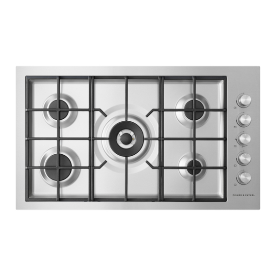
Fisher & Paykel CG905DW Installation Manual
Hide thumbs
Also See for CG905DW:
- Installation instructions and user manual (60 pages) ,
- User manual (28 pages) ,
- Installation instructions manual (17 pages)
Table of Contents
Advertisement
Quick Links
Advertisement
Table of Contents

Summary of Contents for Fisher & Paykel CG905DW
- Page 1 GAS COOKTOP CG905DW models INSTALLATION GUIDE GB IE 590875B 08.17...
-
Page 2: Important Safety Instructions
SAFETY AND WARNINGS IMPORTANT SAFETY INSTRUCTIONS WARNING! Electrical Shock Hazard This appliance must be installed and serviced only Before carrying out any work on the ● by a suitably qualified and registered person, and in electrical section of the appliance, it must be accordance with the current editions of the following disconnected from the mains electricity supply. - Page 3 SAFETY AND WARNINGS Ventilation requirements Before you install the appliance, please make sure that The appliance should be installed in a room or space the local distribution conditions (nature of gas and ● ● with an air supply in accordance with BS 5440:2 2009. pressure) and the adjustment of the appliance are For rooms with a volume of less than 5 m , permanent...
- Page 4 SAFETY AND WARNINGS When you install the appliance As servicing requires removing of the cooktop from the ● countertop we do not recommend flush mounting. To the fullest extent permissible by law, the owner carries all risk for flush mounting of the cooktop. The owner must ensure the cooktop has been cut out from the benchtop before servicing can be carried out.
-
Page 5: Parts Supplied
GAS RATE SUMMARY All appliances are factory set for either Natural Gas or LPG. Check the ‘Gas type’ sticker on the base of the appliance. SEMI-RAPID SEMI-RAPID DUAL WOK RAPID CG905DW BURNER SEMI-RAPID RAPID DUAL WOK GAS TYPE Jet size... - Page 6 PRODUCT & CABINETRY DIMENSIONS Note: Gas inlet connection is located in the rear right corner. FRONT REAR SIDE PRODUCT DIMENSIONS Overall height of product (excluding burners, dials and pan supports) Overall width of product Overall depth of product Height of chassis (below top of counter) Width of chassis Depth of chassis...
-
Page 7: Clearance Dimensions
CLEARANCE DIMENSIONS FRONT CLEARANCE DIMENSIONS Minimum clearance from left edge of cutout to nearest combustible surface Minimum clearance from right edge of cutout to nearest combustible surface Minimum clearance from rear edge of cutout to: Nearest combustible surface Nearest non-combustible surface Minimum height of non-combustible material when used on adjacent walls Minimum clearance from cooktop surface to: Rangehood... - Page 8 FLUSH MOUNTING INSTALLATION (OPTIONAL) IMPORTANT! Refer to ‘When you you install the appliance’ in the Safety and Warnings section before you flush mount this appliance. Note: Electrical connection is made at the right rear FRONT SIDE REAR PRODUCT AND CABINETRY DIMENSIONS Overall height of product (excluding burners, dials and pan supports) Overall width of product...
- Page 9 FLUSH MOUNTING INSTALLATION (OPTIONAL) ROUTER THE BENCHTOP TO THE SPECIFIED DEPTH FIT THE CLAMPING BRACKETS MASK OFF THE AREA TO BE SILICONED 3/4” - 2” (19 mm - 50 mm) REPEAT ON ALL THE OTHER SIDES (Total 6 brackets) 3 mm 5 mm IF REMOVING PRODUCT, CUT AROUND THE SILICONE...
- Page 10 DISCARD PACKAGING FIT THE NIPPLE AND WASHER Model may vary from illustrations shown IMPORTANT! - Use gas tape to seal the connection Nipple (1/2” BSPT thread) Nipple (½” NPT thread) Recycle responsibly LOWER GENTLY INTO THE CUTOUT...
-
Page 11: Gas Connection
SECURE TO COUNTERTOP WITH BRACKETS BASED ON THE COUNTERTOP THICKNESS Place the cooktop into the cutout and tighten it with the supplied clamps. These will cope with the countertop thicknesses 19 - 50 mm when used in the two REPEAT ON ALL THE OTHER SIDES orientations shown. -
Page 12: Leak Testing
LEAK TESTING Leak testing of the appliance shall be conducted according to the manufacturer’s instructions. ● The appliance and its individual shut-off valve must be disconnected from the gas supply piping system during ● any pressure testing of that system in excess of 3.5mbar. Maximum inlet gas supply pressure 50 mbar. -
Page 13: Test Operation
INSTALLATION INSTRUCTIONS AFFIX DUPLICATE DATA LABEL SOMEWHERE FIT PAN SUPPORTS ACCESSIBLE & PLUG COOKTOP IN Duplicate data label TEST OPERATION To check that the ignition system operates correctly, light each burner by itself, then all burners in combination. ● Check for a well-defined blue flame without any yellow tipping. ●... -
Page 14: Final Checklist
FINAL CHECKLIST TO BE COMPLETED BY THE INSTALLER Have you installed the clamping brackets? Have you verified that the type of model (factory-set for NG or LPG) matches the type of gas at the site of installation? Have you sealed all connections with gas tape? Have you leak-tested all connections? Is the cooktop set to the correct working pressure? Have you affixed the supplied duplicate data plate label on an adjacent... - Page 16 FISHERPAYKEL.COM © Fisher & Paykel Appliances 2017. All rights reserved. The product specifications in this booklet apply to the specific products and models described at the date of issue. Under our policy of continuous product improvement, these specifications may change at any time. You should therefore check with your Dealer to ensure this booklet correctly describes the product currently available.


Need help?
Do you have a question about the CG905DW and is the answer not in the manual?
Questions and answers