Advertisement
Quick Links
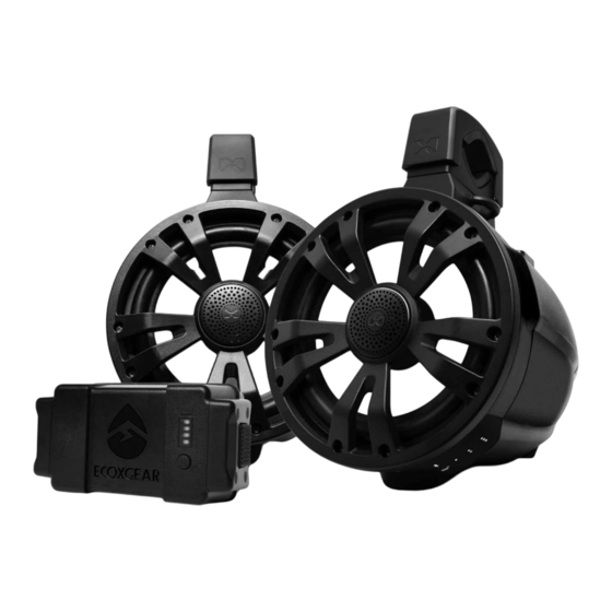
8 inch Tower Speakers
Installation Guide
ExtremeTower TA8
Models: SEI-ETAMP7700...20
Bluetooth Amplified
1
Tower Speaker
1
Passive Tower Speaker
ExtremeTower
Built-in Amplifier
ExtremeTower TB8
Models: SEI-ETBAT7700...20
Bluetooth Amplified
1
Tower Speaker
1
Passive Tower Speaker
1
Battery
Advertisement

Related Manuals for EcoxGear SEI-ETAMP7700 20 Series


Summary of Contents for EcoxGear SEI-ETAMP7700 20 Series
- Page 1 ExtremeTower 8 inch Tower Speakers Built-in Amplifier Installation Guide ExtremeTower TA8 ExtremeTower TB8 Models: SEI-ETAMP7700...20 Models: SEI-ETBAT7700...20 Bluetooth Amplified Bluetooth Amplified Tower Speaker Tower Speaker Passive Tower Speaker Passive Tower Speaker Battery...
- Page 2 Important · Please read the Hardware Guide, this Installation Guide, and the User Guide before installation and use. · This Installation Guide is for the TA8 (SEI-ETAMP7700...20) and TB8 (SEI-ETBAT7700...20) ExtremeTower Speakers. The TA8 Speakers do NOT include a removable, rechargeable battery. You can purchase the battery separately.
-
Page 3: Product Warranty
Important · When mounting the speaker, it is extremely important to make sure that the mount is secure and will not cause any potential issues. Please check that the speaker does NOT block the driver’s view or prevents the safe operation of your boat or other vehicle. Ensure that all screws are tightened and the speaker is secured correctly so that the speaker will NOT fall. - Page 4 ExtremeTower Overview ExtremeTower Passive Speaker Layout Tweeter Party Lights Speaker U-Shaped Pin Quick-Release Knob Rotating 360° Top Mount Mount Clamp Clamp Bottom Mount Base-Mount Clamp...
- Page 5 ExtremeTower Overview ExtremeTower Amplified Speaker Layout Battery Pack Switches Control Buttons Waterproof Back Cover Back Cover Latch Dome Light Release Button...
- Page 6 ExtremeTower Overview Audio, LED Control Signals, and Power Connectors and Cables Amplified Tower Speaker and Passive Tower Speaker · Your package has one Amplified Tower Speaker and one Passive Tower Speaker. · The Passive Tower Speaker must be connected to the Amplified Tower Speaker to receive audio and LED control signals.
- Page 7 ExtremeTower Overview Speaker Connector Jacks Each speaker has 2 types of Connector Jacks. 9-Pin Aviation Connector Jack 6-Pin Aviation Connector Jack 6-Pin Deutsch Connector Jack 4-Pin Deutsch Connector Jack 6-Pin Deutsch Connector Jack 1. A round Aviation Connector Jack is inside the speaker Base-Mount, which allows the cable to pass through the Bottom Mount Clamp and go into a hole in the crossbar at the location where the speaker is mounted.
- Page 8 ExtremeTower Overview This is also the connection suggested if you want to utilize the Quick-Release-Mount option. The Amplified Tower Speaker has both a 4-pin and a 6-pin, square connector jack. The Passive Tower Speaker only has a 6-pin square connector jack. FM Dipole Antenna Jack FM Dipole Antenna Jack...
- Page 9 ExtremeTower Overview INT EXT 3. Open the Back Cover (refer to Install the Rechargeable Battery Pack to the Amplified Speaker for details), move the (Blue) FM ANT Switch to the EXT position. Cables Your package includes 2 Cable Sets for each wiring option. 1.
- Page 10 ExtremeTower Overview 6-Pin Aviation Connector 6 Bullet Connectors (Input) “Round A2” 6-Pin Pass-Through LED and Speaker Aviation Cable · The short cable (“Round A2” 6-pin pass-through Aviation Cable) has a 6-pin round connector on one end and 6 bullet connectors on the other end.
- Page 11 ExtremeTower Overview 6-Pin Deutsch 6-Pin Deutsch Connector Connector “Deutsch A2” 6-Pin LED and Speaker Deutsch Cable · 6-pin Deutsch connector for interconnection between the Amplified Tower Speaker and the Passive Tower Speaker.
-
Page 12: Installation And Wiring
Installation and Wiring Installation and Wiring Procedure 1: Round Aviation Cable If you choose to use the Aviation Cable Set for wiring your ExtremeTower Speakers, follow the steps below. Speaker and LED Lighting Control Wiring The Aviation Cable will pass through the Bottom Mount Clamp and go into a hole in the crossbar;... - Page 13 Installation and Wiring 3. Pull out the 9 wires from the hole, make the following wire connections and use heat-shrink tubing or electrical tape to seal the connections: · Connect the 6 bullet connectors on “Round A1” to those on the “Round A2”...
- Page 14 Installation and Wiring Mount the Amplified Tower Speaker to the Crossbar 1. Base-Mount: Remove the tape and pull out a small plastic bag from the Base-Mount. This bag has one Aviation Connector Jack Cap. You don’t need this cap for this installation, but save the cap for later use in case you change the wiring methods.
- Page 15 Installation and Wiring 4. Connect the (9-pin round) Aviation Connector to the Aviation Connector Jack on the Amplified Speaker. Tighten the connector clockwise with a long nose plier (not included) or similar tool. IMPORTANT: Tighten the connector to ensure the connection is waterproof to avoid potential water or moisture penetration into the jack connector pins, causing damage to the speaker.
- Page 16 Installation and Wiring M5 Allen wrench (or with your hand if utilizing the Quick-Release Knob). Note: It is NOT recommended to use the Quick-Release Knob with this wiring method. Do NOT tighten the screw yet. Bolts Washers and Spring Washers Top Clamp Rubber Insert 9.
- Page 17 Installation and Wiring Mount the Passive Tower Speaker to the Crossbar 1. Base-Mount: Remove the tape and pull out a small plastic bag from the Base-Mount. This bag has one Aviation Connector Jack Cap. You don’t need this cap for this installation, but save the cap for later use in case you change the wiring methods.
- Page 18 Installation and Wiring Installation and Wiring Procedure 2: Square Deutsch Cable This cable installation method does NOT require that the cables go through the mount. This method allows for the speakers to be mounted to the crossbar before running the wires and before completing the cable connections.
- Page 19 Installation and Wiring Mount the Amplified Tower Speaker to the Crossbar Rubber Insert Swivel Flange and Bottom Clamp Assembly 4 pcs M3 x 10 Screws Base Cover Plate 1. Put the appropriate Lower Rubber Insert onto the Swivel Flange and Bottom Clamp Assembly. 2.
- Page 20 Installation and Wiring U-Shaped Pin Quick-Release Knob 4. Insert the U-Shaped Pin into the two holes on the side of the Base-Mount. Insert the pins into the holes on the left side of the Mount when viewing from the rear of the speaker. 5.
- Page 21 Installation and Wiring Bolts Washers and Spring Washers Top Clamp Rubber Insert 6. Put the Upper Rubber Insert on the Top Clamp. Align the rubber groove with the bulge of the Top Clamp and press down to assemble the Clamp and Rubber Insert. 7.
- Page 22 Installation and Wiring 2. Remove the 4-pin/6-pin Rubber Plug from the Deutsch Connector Jacks on each speaker and connect the Amplified Tower Speaker and Passive Tower Speaker with the supplied (“Deutsch A2” 6-pin) Deutsch Interconnection Cable. Plug in the Deutsch Connector into the 6-pin Deutsch Jack on each speaker.
- Page 23 Installation and Wiring 4. Plug in the 4-pin Deutsch Power Cable’s connector into the 4-pin Deutsch Connector Jack on the Amplified Speaker. IMPORTANT: For the TB8 (SEI-ETBAT7700...20) ExtremeTower Speakers, if you do not connect the Amplified Tower Speaker to the vehicle battery, (e.g., “Deutsch A1” 4-pin Power Cable is NOT used) you MUST seal the 4-pin Deutsch Connector Jack by plugging in the included 4-pin Deutsch Rubber Plug, to prevent potential water or moisture penetration into the jack.
- Page 24 Installation and Wiring Connecting Your Speaker to a +12V Power Supply and Powering On Black Cable Red Cable Remote Turn-On Extension Cable 1. Once you complete one of the Installation Procedures, you can connect the 3 wires (+12V, GND, and Remote Turn-On) on the Power Cables (or Extension Cables, if needed) to the vehicle’s battery and ignition signal terminal.
- Page 25 Installation and Wiring Install the Rechargeable Battery Pack on the Amplified Speaker Note: The following instructions are for the TB8 (SEI-ETBAT7700...20) ExtremeTower Speakers. If your package has a rechargeable battery, follow the steps below to install your Battery Pack on the Amplified Speaker. (The TA8 Speakers do NOT include a removable, rechargeable battery.
- Page 26 Installation and Wiring Port Cap to protect the Battery Pack’s connection area on the speaker from water, dirt and damage. 4. Place the Cover back on the speaker and turn clockwise until the latch is locked. IMPORTANT: When you put Cover back, make sure the Cover is closed properly.
- Page 27 Next, read your User Guide to explore more features and functions for your ExtremeTower Speakers...
Need help?
Do you have a question about the SEI-ETAMP7700 20 Series and is the answer not in the manual?
Questions and answers