Table of Contents
Advertisement
Quick Links
Advertisement
Table of Contents

Related Manuals for THORLABS LDM21


Summary of Contents for THORLABS LDM21
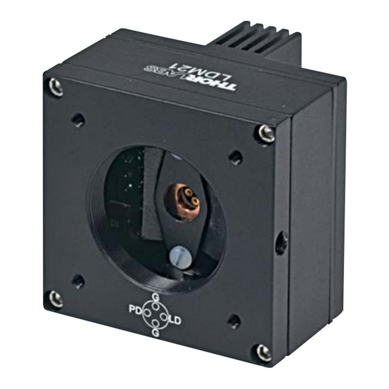
- Page 1 LDM21(/M) 5.6 mm/9 mm Laser Diode Mount User Guide ...
- Page 2 ...
-
Page 3: Table Of Contents
Operation ............ 1 2 Chapter 5 Troubleshooting .......... 1 4 Chapter 6 Specifications ............. 1 6 Chapter 7 Mechanical Drawing ........... 17 Chapter 8 Warranty and RMA Information ...... 1 8 Chapter 9 Thorlabs Worldwide Contacts ...... 1 9 ... -
Page 5: Chapter 1 Safety
5.6 mm/ 9 mm Laser Diode Mount Chapter 1: Safety Chapter 1 Safety Warning This unit must not be operated in explosive environments. Warning Avoid exposure – laser radiation emitted from apertures Rev. L, March 23, 2023 Page 1 ... -
Page 6: Chapter 2 Description
Controllers, a laser diode can be operated with precise temperature control for wavelength and power stability. A four pin socket accepts all 9 mm and 5.6 mm laser diodes. Easy to use polarity switches allow the laser mount to be configured for all possible laser pin assignments. The LDM21(/M) was designed with features that allow it to be easily incorporated into complex systems. The front of the LDM21(/M) has an SM1 (1.035"‐40) thread to accept a wide variety of Thorlabs SM1 1.0" optics mounts and accessories. Also standard with the mount are 4‐40 tapped holes on 30 mm centers for mounting any number of Thorlabs ... -
Page 7: Chapter 3 Setup
5.6 mm/ 9 mm Laser Diode Mount Chapter 3: Setup Chapter 3 Setup Laser Installation 1. Unpack the laser mount and remove the four 2‐56 socket‐head screws from the front cover using a 5/64" hex driver (provided). 2. Remove the two Phillips head 2‐56 screws from the laser‐ mounting flange and remove the flange. 3. Determine the laser pin configuration from the laser diode manufacturer’s data sheets and set the LD (Laser Diode) and PD (Photodiode) switches located on the inside of the unit according to Figure 2. Case Style A Case Style B Case Style C Case Style D... - Page 8 Most laser diodes are three pins with the case tied to one of the laser pins and also to one of the photodiode pins. The other laser and photodiode pins will be isolated from the case. The LDM21(/M) was designed to operate the laser case at ground potential, therefore this common pin will be inserted into either the 12 o’clock or the 6 o’clock position of the laser connector. Locate the isolated laser pin and insert it in the 3 o’clock position. The isolated photodiode should now be in the 9 o’clock position. Refer to Fig. 3. (Orient the mount with the PD polarity switch ...
- Page 9 5.6 mm/ 9 mm Laser Diode Mount Chapter 3: Setup Figure 3 LD and PD Orientation 5.6 mm Adapter By default, the LDM21(/M) is designed to be used with standard 9 mm laser diode packages. The mount can be used with a standard 5.6 mm using the included adapter, which can be found in the small brown envelope marked “Accessories” on the outside. Included in this envelope is the 9 mm mounting plate and the imperial to metric mounting adapter. 4‐Pin Laser Diodes The LDM21(/M) also supports 4‐pin laser diodes. Insert the laser into the 4‐pin socket and note which laser pin is in the 3 o’clock position (laser anode or cathode). Also note which photodiode pin is in the 9 o’clock ...
- Page 10 5.6 mm/ 9 mm Laser Diode Mount Chapter 3: Setup Laser Controller Connections Using the Thorlabs LDC/ITC Series Laser Controllers: The LDM21(/M) is compatible with all Thorlabs LDC LD controllers and ITC series combination controllers (LD and TEC). Appropriate cables with DB9 connectors are included with Thorlabs controllers and ensure that the controllers cannot be connected incorrectly. Additionally, these controllers have built‐ in protection circuitry that protects the laser when not in use. The nomenclature for the Laser Diode polarity switch on the ...
- Page 11 3 (Case) switches. i.e., if the LD and PD switches are set to AG, then this pin grounds the Anodes of the laser and photo diode. This pin is connected to the 9 o’clock pin on the laser socket with the PD Polarity Switch is set to Photodiode CG (Cathode Grounded). It is attached to ground 4 Anode and the 12 o’clock and 6 o’clock pins on the laser socket when the PD Polarity Switch is set to AG (Anode Grounded). This pin is the return side of the Interlock Interlock 5 circuitry. Pins 1 and 5 are shorted internally in Return the LDM21(/M). 6 N/A This pin is connected to the 3 o’clock pin on the Laser Diode laser socket when the LD Polarity Switch is set to 7 Cathode AG (Anode Grounded). If the pin is not connected, it will be floating This pin is connected to the 3 o’clock pin on the Laser Diode laser socket when the LD Polarity Switch is set to 8 Anode CG (Cathode Grounded). If the pin is not connected, it will be floating 9 N/A ...
- Page 12 5.6 mm/ 9 mm Laser Diode Mount Chapter 3: Setup TEC Controller Connections Using the Thorlabs TED Series TEC Controllers: The LDM21(/M) is best used with Thorlabs TED200C or related TEC Controllers. The TED series are shipped with a mating DB9 cable that plugs directly into the controller and laser mount. Using the cable supplied with the TED, the controller cannot be connected incorrectly. Simply connect the cable included with the TED to the Laser Mount and to the controller. Using a third‐party TEC controller: When using a third‐party controller, a custom cable will have to be made to properly interface to the laser mount. Please refer to the table below for laser connections. Pin Signal Description 1 N/A N/A The 10 kΩ @ 25 °C NTC thermistor (provided for ...
- Page 13 5.6 mm/ 9 mm Laser Diode Mount Chapter 3: Setup Thermistor Data Resistance (Ω) °C Resistance (Ω) °C 15895 15 9563 26 15153 15 9149 27 14451 17 8755 28 13785 18 8380 29 13155 19 8023 30 12558 ...
-
Page 14: Theoretical Resistance Values
Unit A ‐14.6337 ‐ B 4791.842 K C ‐115334 D 3.730535E+06 3.354016E‐03 ‐ 1 ‐1 2.569850E‐04 1 ‐2 2.620131E‐06 1 ‐3 6.383091E‐08 1 298.15 K 0 10000 Ω ref Mounting Other Accessories The LDM21(/M) includes a SM1 threaded hole centered on the laser for mounting Thorlabs SM1‐series optic mounts. This is most often used for mounting aspheric collimating optics available separately from Thorlabs. Page 10 TTN013394‐D02 ... - Page 15 5.6 mm/ 9 mm Laser Diode Mount Chapter 3: Setup Also included are four 4‐40 tapped holes mounted on 30 mm centers for attaching our cage assembly products. Using the combination of the SM1 threaded mount and the cage assemblies’ products, a wide variety of optical systems can be easily assembled from off‐the‐shelf products. Rev. L, March 23, 2023 Page 11 ...
-
Page 16: Operation
35 °C. Operating the LDM21(/M) outside of the safe operating area will result in thermal runaway of the cooling system which will damage the laser diode mounted in the unit. Additionally, the 2 W maximum cooling capacity includes the power ... - Page 17 5.6 mm/ 9 mm Laser Diode Mount Chapter 4: Operation Maintaining the LDM21(/M) There are no serviceable parts in the LDM21(/M). The housing may be cleaned by wiping with a soft damp cloth. If you suspect a problem with your LDM21(/M), please call Thorlabs Technical Support, and an engineer will be happy to assist you. Rev. L, March 23, 2023 Page 13 ...
-
Page 18: Chapter 5 Troubleshooting
2. Laser wavelength or power is unstable even though the TEC controller shows a stable temperature. Make sure that your laser diode is fully inserted into the LDM21(/M) laser socket and that its body is in full contact with the copper cold plate. Make sure that the appropriate mounting flange is installed over your laser. There are two different flanges; one ... - Page 19 5.6 mm/ 9 mm Laser Diode Mount Chapter 5: Troubleshooting or the “G” socket at 6 o’clock. Refer to your laser diode data for pin orientation. If your cathode pin is common to the body of your laser diode, set the LD polarity switch to “CG”. If your anode pin is common to the body of your laser diode, set the LD polarity switch to “AG”. The setting for the PD polarity switch is irrelevant. If you still have problems or questions regarding the operation of your LDM21(/M), please contact Thorlabs Tech Support. Rev. L, March 23, 2023 Page 15 ...
-
Page 20: Chapter 6 Specifications
5.6 mm/ 9 mm Laser Diode Mount Chapter 6: Specifications Chapter 6 Specifications Item # LDM21(/M) General 1.75" x 1.75" x 1.66" Size (44.5 mm x 44.5 mm x 42.1 mm) Weight 3 oz (0.08 kg) 1.035"‐40 Thread for SM1 Series Optics Mounts Accessory Mounting 4‐40 x 30 mm Tapped Holes for Cage Assembly Products Mounting Holes LDM21: 8‐32 or LDM21/M: M4 Laser Specifications Lasers Supported 5.6 mm and 9 mm Max Laser Current 500 mA a Max Laser Input Power 600 mW Ø5.6 and Ø9.0 mm Laser Diodes Laser Pin A, B, C, D, E, and H Configurations Configurations Selectable Laser Polarity Select Slide Switches Laser Interface DB9 Female TEC Specifications Max TEC Current 2.5 A Max TEC Voltage ... -
Page 21: Chapter 7 Mechanical Drawing
5.6 mm/ 9 mm Laser Diode Mount Chapter 7: Mechanical Drawing Chapter 7 Mechanical Drawing Rev. L, March 23, 2023 Page 17 ... -
Page 22: Chapter 8 Warranty And Rma Information
Annex I category electrical and electronic equipment sold after August 13, 2005 to Thorlabs, Annex I without incurring disposal charges. Eligible units are marked with the crossed out “wheelie bin” logo (see right), were sold to and are currently owned by a company or institute within the EC and are not dissembled or contaminated. Contact Thorlabs for more information. Waste treatment is your own responsibility. “End of life” units must be returned to Thorlabs or handed to a company specializing in waste recovery. Do not dispose of the unit in a litter bin or at a public waste disposal site. It is the user’s responsibility to delete all private data stored on the device prior to disposal. Return of Devices This precision device is only serviceable if returned and properly packed into the complete original packaging including the complete shipment plus the cardboard insert that holds the enclosed devices. If necessary, ... -
Page 23: Chapter 9 Thorlabs Worldwide Contacts
5.6 mm/ 9 mm Laser Diode Mount Chapter 9: Thorlabs Worldwide Contacts Chapter 9 Thorlabs Worldwide Contacts For technical support or sales inquiries, please visit us at for our most up‐to‐date contact information. www.thorlabs.com/contact USA, Canada, and South America UK and Ireland Thorlabs, Inc. Thorlabs Ltd. sales@thorlabs.com sales.uk@thorlabs.com techsupport@thorlabs.com techsupport.uk@thorlabs.com Europe Scandinavia Thorlabs GmbH Thorlabs Sweden AB europe@thorlabs.com scandinavia@thorlabs.com France Brazil Thorlabs SAS Thorlabs Vendas de Fotônicos Ltda. sales.fr@thorlabs.com brasil@thorlabs.com Japan China Thorlabs Japan, Inc. Thorlabs China sales@thorlabs.jp chinasales@thorlabs.com ... - Page 24 www.thorlabs.com ...
Need help?
Do you have a question about the LDM21 and is the answer not in the manual?
Questions and answers