Table of Contents
Advertisement
Quick Links
Advertisement
Table of Contents

Related Manuals for THORLABS LDM21


Summary of Contents for THORLABS LDM21
- Page 1 LDM21 5.6 mm/9 mm Laser Diode Mount User Guide...
-
Page 3: Table Of Contents
3.3. 4‐Pin Laser Diodes ............ 5 3.4. Laser Controller Connections .......... 5 3.5. TEC Controller Connections .......... 6 3.6. Thermistor Data ............ 7 3.7. Mounting Other Accessories .......... 9 Chapter 4 Operation ................. 10 4.1. Safe Operating Area ............ 10 4.2. Maintaining the LDM21 .......... 11 Chapter 5 Troubleshooting ............. 12 Chapter 6 Specifications ..............13 Chapter 7 Mechanical Drawing ............ -
Page 4: Chapter 1 Warning Symbol Definitions
LDM21 Chapter 1: Warning Symbol Definitions Chapter 1 Warning Symbol Definitions Below is a list of warning symbols you may encounter in this manual or on your device. Symbol Description Direct Current Alternating Current Both Direct and Alternating Current Earth Ground Terminal... -
Page 5: Chapter 2 Description
25 °C in a typical laboratory ambient environment (20 to 30 °C). Please refer to the Safe Operating Area chart in this manual to ensure that the LDM21 is used within its capabilities. -
Page 6: Chapter 3 Setup
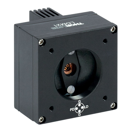
LDM21 Chapter 3: Setup Chapter 3 Setup 3.1. Laser Installation Unpack the laser mount and remove the four 2-56 socket-head screws from the front cover using a 5/64" hex driver (provided). Remove the two Phillips head 2-56 screws from the laser-mounting flange and remove the flange. - Page 7 Refer to Fig. 3. (Orient the mount with the PD polarity switch above the LD socket). The LDM21 Mount is also compatible with style E and style H laser diodes, which do not have a photodiode; they have only a laser diode and a ground pin.
-
Page 8: 5.6 Mm Adapter
3.2. 5.6 mm Adapter By default, the LDM21 is designed to be used with standard 9 mm laser diode packages. The mount can be used with a standard 5.6 mm using the included adapter, which can be found in the small brown envelope marked “Accessories”... -
Page 9: Tec Controller Connections
Using the Thorlabs TED Series TEC Controllers: The LDM21 is best used with Thorlabs TED200 or related TEC Controllers. The TED series are shipped with a mating DB9 cable that plugs directly into the controller and laser mount. Using the cable supplied with the TED, the controller cannot be connected incorrectly. -
Page 10: Thermistor Data
This pin is connected to the negativeterminal of the TEC -TEC (-) element. The negative terminal of the AD592 temperature transducer. When using Thorlabs TEDs, no external AD592 (-) circuitry is required. To use this device with third party controllers, it must be properly biased. Refer to Analog Devices AD592 Data for applications information. - Page 11 LDM21 Chapter 3: Setup Resistance (Ω) °C Resistance (Ω) °C 15895 9563 15153 9149 14451 8755 13785 8380 13155 8023 12558 7684 11991 7362 11454 7055 10944 6762 10460 6484 10000 Theoretical Resistance Values The relationship between resistance and temperature can also be calculated...
-
Page 12: Mounting Other Accessories
Chapter 3: Setup 3.7. Mounting Other Accessories The LDM21 includes a SM1 threaded hole centered on the laser for mounting Thorlabs SM1-series optics mounts. This is most often used for mounting aspheric collimating optics available separately from Thorlabs. Also included are four 4-40 tapped holes mounted on 30 mm centers for attaching our cage assembly products. -
Page 13: Chapter 4 Operation
4.1. Safe Operating Area The LDM21 is intended to be operated at a fixed temperature set-point of 25 °C but can be operated as low as 20 °C as long as the input power to the laser diode (input current x LD voltage) does not exceed the values specified in the Safe Operating Area curve as a function of ambient temperature. -
Page 14: Maintaining The Ldm21
There are no serviceable parts in the LDM21. The housing may be cleaned by wiping with a soft damp cloth. If you suspect a problem with your LDM21, please call Thorlabs Technical Support, and an engineer will be happy to assist you. -
Page 15: Chapter 5 Troubleshooting
“CG”. If your Anode pin is common to the body of your laser diode, set the LD polarity switch to “AG”. The setting for the PD polarity switch is irrelevant. If you still have problems or questions regarding the operation of your LDM21, please contact Thorlabs Tech Support. TTN013394-D02... -
Page 16: Chapter 6 Specifications
LDM21 Chapter 6: Specifications Chapter 6 Specifications Item # LDM21 General Size 1.75" x 1.75" x 1.47" Weight 3 oz 1.035"-40 Thread for SM1 Series Optics Mounts Accessory Mounting 4-40 x 30 mm Tapped Holes for Cage Assembly Products Miscellaneous... -
Page 17: Chapter 7 Mechanical Drawing
SERIES THREAD 0.12 30MM CAGE ASSEMBLY 1.75 LASER DIODE CONNECTION MOUNTING HOLES FEMALE DB9 (#4-40) 4 PLACES #8-32 MOUNTING HOLE 4 PLACES 0.88 0.12 0.12 0.88 0.99 TEC CONNECTION MALE DB9 Figure 5 Mechanical Drawing of the LDM21 TTN013394-D02 Page 14... -
Page 18: Chapter 8 Regulatory
8.1. Waste Treatment is Your Own Responsibility If you do not return an “end of life” unit to Thorlabs, you must hand it to a company specialized in waste recovery. Do not dispose of the unit in a litter bin or at a public waste disposal site. -
Page 19: Chapter 9 Thorlabs Worldwide Contacts
LDM21 Chapter 9: Thorlabs Worldwide Contacts Chapter 9 Thorlabs Worldwide Contacts For technical support or sales inquiries, please visit us at www.thorlabs.com/contact for our most up-to-date contact information. USA, Canada, and South America UK and Ireland Thorlabs, Inc. Thorlabs Ltd. - Page 20 www.thorlabs.com...
Need help?
Do you have a question about the LDM21 and is the answer not in the manual?
Questions and answers