
Subscribe to Our Youtube Channel
Related Manuals for THORLABS DC3100 Series


Summary of Contents for THORLABS DC3100 Series
- Page 1 Operation Manual Thorlabs Instrumentation LED Illumination System for Fluorescence Lifetime Imaging (FLIM) DC3100 2009...
- Page 2 Version: Date: 04.09.2009 © 2009 Thorlabs...
-
Page 3: Table Of Contents
Contents Foreword 1 General Information ........................... 4 1.1 Safety ........................... 7 1.2 Ordering Codes and Accessories 2 Getting Started ........................... 8 2.1 Unpacking ........................... 8 2.2 Preparation ........................... 9 2.3 Operating Elements 2.3.1 Operating Elements on the Front Panel ................................. 9 ................................. - Page 4 LED @ 470nm 7.3.3.4 ..............................42 LED @ 630nm ........................... 44 7.4 Letter of Volatility ........................... 45 7.5 Thorlabs 'End of Life' Policy (WEEE) ................................. 45 7.5.1 Waste Treatment on your own Responsibility ................................. 45 7.5.2 Ecological Background ........................... 46 7.6 List of Acronyms...
-
Page 5: Foreword
We and our international partners are looking forward to hearing from you. Thorlabs GmbH This part of the instruction manual contains every specific information on how to handle and use the DC3100 - FLIM LED Driver. -
Page 6: General Information
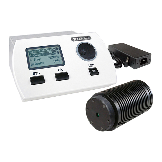
Fluorescence Lifetime Imaging (FLIM) and other microscopy applications that require modulated high-power LED illumination sources. The compact LED driver in the DC3100 series can supply a high current (up to 1A) to high-power LEDs. The DC3100 series system includes an optical head, modulating electronics, and a heat sink designed to dissipate the heat generated by high-power LEDs. - Page 7 1 General Information CAUT ION The head of DC3100 can contain an UV light LED! In this case the LED radiates intense UV light during operation. Precautions must be taken to prevent looking directly at the UV light with unprotected eyes. Do not look directly into the UV light or look through the optical system during operation of the device.
- Page 8 Thorlabs GmbH is not responsible for any radio television interference caused by modifications of this equipment or the substitution or attachment of connecting cables and equipment other than those specified by Thorlabs GmbH. The correction of interference caused by such unauthorized modification, substitution or attachment will be the responsibility of the user.
-
Page 9: Ordering Codes And Accessories
DC3100 - FLIM LED Driver with LED Head @ 470nm DC3100-630 DC3100 - FLIM LED Driver with LED Head @ 630nm Other wavelengths on request ranging from 365nm up to 940nm. Please visit our homepage http://www.thorlabs.com for further information. DC3100... -
Page 10: Getting Started
1 General Information Getting Started Unpacking Inspect the packaging for damage. If the shipping container seems to be damaged, keep it until you have inspected the contents and you have inspected the DC3100 mechanically and electrically. Verify that you have received the following items: 1. -
Page 11: Operating Elements
2 Getting Started After the device is powered up, the graphics display will show a 'Welcome' screen for a few seconds. The DC3100 is immediately ready to use after turning on. The rated accuracy is reached, however, after a warming-up period of approximately 10 minutes. Operating Elements 2.3.1 Operating Elements on the Front Panel... -
Page 12: Operating Elements On The Rear Panel
2 Getting Started 2.3.2 Operating Elements on the Rear Panel Figure 3 Operating Elements on the Rear Panel 2.3.3 Operating Elements on the LED Head Figure 4 Operating Elements on the LED Head DC3100... -
Page 13: Operating The Dc3100
2 Getting Started Operating the DC3100 The DC3100 can either be controlled via the front panel of the main unit (see chapter Operation and Settings) or by a remote application (see chapter Remote Application). Operation and Settings The following sub chapters contain the description about the operation of the DC3100. -
Page 14: Operation Modes
3 Operating the DC3100 3.1.2 Operation Modes Only if one of the three operation modes (Constant Current, Internal Modulation or External Control) is selected the LED can be enabled /switched on. It is possible to leave the active mode when the LED is switched on and enter the main menu. - Page 15 3 Operating the DC3100 To change the settings select one of the parameters using the multi-control knob and press the 'Ok' button. The corresponding screen appears and the value for the current, the frequency or the modulation depth can be adjusted with the multi-control knob.
-
Page 16: External Control Mode
3 Operating the DC3100 Figure 12 Definition of the Parameter Current and Modulation Depth 3.1.2.3 External Control Mode This mode allows to control the DC3100 by an external signal. The 'External Control Mode' has no parameter settings. The LED can only be controlled via the BNC connector at the rear panel of the DC3100. -
Page 17: Settings And Configuration
3 Operating the DC3100 The last selected operation mode will be saved. After switching on the DC3100 again this operation mode will be automatically the active mode. All settings are saved and validated after a shut off. The current settings in the 'Constant Current Mode' and in the 'Internal Modulation Mode' are two separate parameters and will be handled individually. -
Page 18: System Settings
3 Operating the DC3100 This menu entry is hidden in normal operation mode. Go to the 'User Limit' screen described above and hold the "LED" button for about three seconds. A sub menu appears and the LEDs maximum current (LED Imax) and frequency (LED fmax) can be set. -
Page 19: About
3.2.1.1 The Installation Menu Before installing the DC3100 remote application, please make sure that no Thorlabs DC3100 - FLIM LED Driver is connected. After you inserted the DC3100 installation CD an autorun menu will appear. If autorun is disabled on your system please browse the installation CD and run "CD-Drive:\Autorun\Autorun.exe". -
Page 20: Installing Visa Runtime Engine
3 Operating the DC3100 Figure 20 Autorun Menu NOTE Please be aware that you need a VISA engine installed on your system to operate the DC3100 remote application. 3.2.1.2 Installing VISA Runtime Engine A VISA runtime 4.3.0 or higher has to be installed on your system to operate the DC3100 remote application. -
Page 21: Installing The Remote Application
3 Operating the DC3100 3.2.1.3 Installing the Remote Application Select "DC3100 - Application software" from the installation menu to start the installation wizard. If you are running Windows VISTA©® you might be promted to change to the "elevated mode", as shown in figure 24. Please ask your administrator for help when you do not have administrator privileges. -
Page 22: Driver Installation
3 Operating the DC3100 Figure 22 The Windows Logo Test 3.2.1.4 Driver Installation The necessary drivers for the DC3100 - FLIM LED Driver is automatically copied to the system folder during the installation of the DC3100 remote application. Attention: The following procedure will only be necessary for Windows XP/2000©®. On the first connection of a device the 'Found New Hardware Wizard' will start to install the new device. -
Page 23: Connecting A Device
3 Operating the DC3100 3.2.2.1 Connecting a Device Please connect the DC3100 to your PC with the shipped USB cable. The USB socket labeled "USB" at the back of the main control. After starting the application the following window is displayed. Figure 23 The Start Screen Use the green button or the menu option 'Connect...' to open the device selection... -
Page 24: Internal Modulation Mode
3 Operating the DC3100 Figure 25 Constant Current Mode 3.2.2.3 Internal Modulation Mode The internal modulation mode can be selected by pressing the 'Internal Modulation Mode' button (see figure 36) or the corresponding menu entry 'Mode/Internal Modulation Mode'. You can either change the values directly by typing into the numeric controls, or use the arrow controls. -
Page 25: User Limit Current
3 Operating the DC3100 This screen is for information purposes only and offers no user inputs. In this mode the LED can only be controlled via the BNC connector at the rear panel of the DC3100. The applied voltage corresponds to the LED current. 1V is equivalent to a LED current of 100mA. -
Page 26: Configuring A New Led
3 Operating the DC3100 Figure 29 User Limit Dialog 3.2.2.6 Configuring a new LED The DC3100 - FLIM LED Driver offers the possibility to operate a LED of your choice. Use the menu 'Configuration/LED Configuration' to set the new LEDs maximum current and frequency. -
Page 27: Changing The Led
3 Operating the DC3100 Figure 32 LED Maximum Frequency Changing the LED The DC3100 - FLIM LED Driver offers the possibility to operate a LED of your choice. Contact Thorlabs for more information! DC3100... -
Page 28: Computer Interface
3 Operating the DC3100 Computer Interface The DC3100 has a USB 2.0 interface that allows to send commands from a host computer to the instrument using the DC3100 - VISA Instrument Driver. The connection between PC and DC3100 is accomplished by an USB cable with a male type 'A' connector at the PC side and a type 'B' connector on the instrument side. -
Page 29: Command Reference
The DC3100 sample applications will be copied to your VXIPNP directory during the driver package installation. The default VXIPNP directory is “C:\VXIPNP” or starting with NI-VISA version 4.2 “C:\Program Files\IVI Foundation”. You can find the sample applications in: „C:\VXIPNP\WinNT\Thorlabs DC3100\sample” „C:\Program Files\IVI Foundation\WinNT\Thorlabs DC3100\sample” Command Reference 4.3.1 Command List Command... - Page 30 4 Computer Interface 4.3.1.1.2 Get User Limit Current Command: DC3100_getLimitCurrent Parameter: None Response: Current limit in Ampere Description: Returns the current limit. 4.3.1.1.3 Set Maximum Current Limit Command: DC3100_setMaxLimit Parameter: Maximum current limit in ampere Response: None Description: Sets the LEDs maximum current limit in ampere. This limit should only be set in case a new LED was installed.
- Page 31 4 Computer Interface 4.3.1.1.9 Set LED OnOff Command: DC3100_setLedOnOff Parameter: LED output state Response: None Description: Sets the LED output. 4.3.1.1.10 Get LED OnOff Command: DC3100_getLedOnOff Parameter: None Response: LED output state Description: Returns the LED output state. 4.3.1.1.11 Set Internal Modulation Current Command: DC3100_setModuCurrent Parameter:...
- Page 32 4 Computer Interface 4.3.1.1.17 Set Constant Current Command: DC3100_setConstCurrent Parameter: Constant current in Ampere Response: None Description: Sets the current in ampere used for the constant current mode. 4.3.1.1.18 Get Constant Current Command: DC3100_getConstCurrent Parameter: None Response: Constant current in ampere Description: Returns the current in Ampere used for the constant current mode.
-
Page 33: Status Reporting
4 Computer Interface 4.3.1.1.24 Revision Query Command: DC3100_revisionQuery Parameter: None Response: Instrument driver revision Firmware revision Description: This function returns the instruments driver revision and the devices firmware revision. Status Reporting The DC3100 stores the status in a register. It can be accessed via the 'DC3100_getStatusRegister. -
Page 34: Maintenance And Repair
If necessary the unit and the display can be cleaned with a cloth dampened with water. The DC3100 does not contain any modules that could be repaired by the user himself. If a malfunction occurs, the whole unit has to be sent back to Thorlabs. Do not remove covers! Firmware Update Firmware upgrades can be done by the user via the USB interface. - Page 35 5 Maintenance and Repair Figure 34 Error Message The following table summarizes possible errors: Error Explanation and Impact Elimination Clipped to The current of the LED was Decrease the input voltage. reduced to the set current limit. Limit Error This happen 'External Control Mode', when a voltage was applied to the...
-
Page 36: Application Note
5 Maintenance and Repair Application Note Fluorescence Lifetime Imaging (FLIM) FLIM (Fluorescence Lifetime Imaging) is an imaging technology that is primarily used with confocal microscopy, but the FLIM method has also been applied in other microscopy methods such as wide field and multiphoton imaging. Especially in the field of cell and tissue research FLIM is a powerful tool to analyze the distribution of biological materials. -
Page 37: Frequency Domain Flim
6 Application Note 6.1.2 Frequency Domain FLIM The lifetime can also be determined in the frequency domain by using a modulated light source. The source continuously emits a sine wave signal in the range of 1 to 200MHz and modulates the fluorescence. Due to the lifetime of the electrons in the excited state there will be a phase shift between the excitation signal and the fluorescence response. -
Page 38: Appendix
6 Application Note Appendix Warranty Thorlabs GmbH warrants material and production of the DC3100 for a period of 24 months starting with the date of shipment. During this warranty period Thorlabs GmbH will see to defaults by repair or by exchange if these are entitled to warranty. -
Page 39: Certifications And Compliances
7 Appendix Certifications and Compliances Certifications and Compliances Category Standards or description Meets intent Directive 89/336/EEC Electromagnetic Declaration Compatibility. Compliance was demonstrated to the following specifications as listed in the Official Journal of the European Conformity - Communities: EN 61326:1997 Electrical equipment for measurement, control and +A1:1998 laboratory use –... - Page 40 7 Appendix Emissions, which exceed the levels required by these standards, may occur when this equipment is connected to a test object. MOD IN port capped at IEC 61000-4-3 test. Performance Criterion C was reached at additional test levels according to EN 61326-1:2006 table 2 DC3100...
-
Page 41: Technical Data
7 Appendix Technical Data 7.3.1 Common Data Line Voltage (Ext. Power Supply) 100 ... 240VAC (-10%, +10%) Line Frequency (Ext. Power Supply) 50 ... 60Hz Power Consumption (max) 20VA Supply mains over Voltage Category II (Cat II) Input Voltage (DC3100 chassis) 12VDC 0 ... -
Page 42: Led For Frequency Domain Flim
7 Appendix DC3100-470 Nominal Wavelength 470nm Maximum Current 1000mA Cut-off Frequency 80MHz DC3100-630 Nominal Wavelength 630nm Maximum Current 1000mA Cut-off Frequency 70MHz depending on LED type and modulation frequency Microscope Mounting are available for the following microscopes: · Olympus BX/IX ·... -
Page 43: Led @ 405Nm
7 Appendix Figure 37 Phase Difference of DC3100-365 7.3.3.2 LED @ 405nm The DC3100-405 contains the UV LED LZ1-00UA05 from LedEngin. The LED emits a wavelength at 405nm and an optical power of up to 1000mW. The 10dB cut-off frequency of the DC3100-405 is 95MHz. The maximum current is 1000mA. -
Page 44: Led @ 470Nm
7 Appendix 7.3.3.3 LED @ 470nm The DC3100-470 contains the blue LED LZ1-00B205 from LedEngin. The LED emits a wavelength at 470nm and an optical power of up to 60lm. The 10dB cut-off frequency of the DC3100-470 is 80MHz. The maximum current is 1000mA. - Page 45 7 Appendix Figure 40 Phase Difference of DC3100-630 DC3100...
-
Page 46: Letter Of Volatility
7 Appendix Letter of Volatility Manufacturer: Thorlabs GmbH Model Number: DC3100 Memory Size Memory Type Volatility User Data Method of Purpose Clearing SRAM (ATmega1281): 8kByte Power down · Program SRAM FLASH Cannot be (ATmega1281): cleared by 128kByte user · Program Code... -
Page 47: Thorlabs 'End Of Life' Policy (Weee)
Waste Treatment on your own Responsibility If you do not return an 'end of life' unit to Thorlabs, you must hand it to a company specialized in waste recovery. Do not dispose of the unit in a litter bin or at a public waste disposal site. -
Page 48: List Of Acronyms
7 Appendix List of Acronyms The following acronyms and abbreviations are used in this manual: Alternating Current AGND Analog Ground Direct Current DGND Digital Ground Dynamic Link Library Federal Communications Commission FLIM Fluorescence Lifetime Imaging Graphical User Interface International Electrotechnical Commission Liquid Crystal Display Light Emitting Diode Personal Computer... -
Page 49: Copyright
Crossed out "Wheelie Bin" Symbol Copyright Thorlabs GmbH has taken every possible care in preparing this User Manual. We however assume no liability for the content, completeness or quality of the information contained therein. The content of this manual is regularly updated and adapted to reflect the current status of the software. -
Page 50: Addresses
7 Appendix Addresses Our Company is represented by several distributors and sales offices throughout the world. Europe Thorlabs GmbH Hans-Boeckler-Str. 6 D-85221 Dachau / Munich Germany Sales and Support Phone: +49 (0) 81 31 / 5956-0 Fax: +49 (0) 81 31 / 5956-99 Email: europe@thorlabs.com... -
Page 51: Index
Index Index - L - LED @ 365nm LED @ 405nm - A - LED @ 470nm LED @ 630nm About LED Configuration Accessories LED Head Addresses LEtter of Volatility Application Note - M - - C - Maintainance Certifications Maximum Current Changing a LED Maximum Frequency... - Page 52 Index - U - Unpacking User Limit User Limit Current Utility Software - V - VISA Installation - W - Warranty WEEE DC3100...
Need help?
Do you have a question about the DC3100 Series and is the answer not in the manual?
Questions and answers